
Page 82 - Biaxial Multiaxial Fatigue and Fracture
P. 82
Micro-Cmck Growth Behavior in Weldmenis of a Nickel-Base Superalloy Under ... 61
specimens were about half those of base metal specimens regardless of the principal strain ratio
and strain range. The broken line in the figure was determined by moving the solid line in the
vertical direction to coincide with the uniaxial data of welded specimens. The exact fatigue
strength reduction factor was about 1.4.
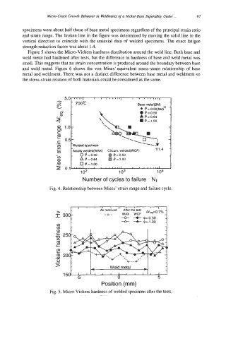
Figure 5 shows the Micro-Vickers hardness distribution around the weld line. Both base and
weld metal had hardened after tests, but the difference in hardness of base and weld metal was
small. This suggests that no strain concentration is produced around the boundary between base
and weld metal. Figure 6 shows the von Mises’ equivalent stress-strain relationship of base
metal and weldment. There was not a distinct difference between base metal and weldment so
the stress-strain relation of both materials could be considered as the same.
-
8 700°C Base metal(BM)
v @=-OSO(bar?’ -
U - 0 4 =-OS0
a
4 A 4 =-0.64
4 =-1.00
E
a 1.0:
m a 1.0:
c
m
c .‘\*\ ..
E
--
4
0
0.5-
.- 0.5- .----
.-
Welded specimen
E E -Welded specimen 111.4 -
-
111.4
welded(WCF)
Circurn.
Axially welded(WAX)
.gj Axially welded(WAX) Circurn. welded(WCF)
.gj
0 @ @=-0.50
4=-0.50
0 4=-0.50
@=-0.50
@
Number of cycles to failure Nf
Fig. 4. Relationship between Mises’ strain range and failure cycle.
Position (mm)
Fig. 5. Micro Vickers hardness of welded specimen after the tests.