
Page 88 - Biaxial Multiaxial Fatigue and Fracture
P. 88
Micro-Crack Growth Behavior in Weldments of a Nickel-Base Superalloy Under ... 13
(a) Uniaxial (b) Torsion, single crack (c) Torsion, X-shaped crack
Fig. 13. Morphology of cracks observed in uniaxial and torsional fatigue tests.
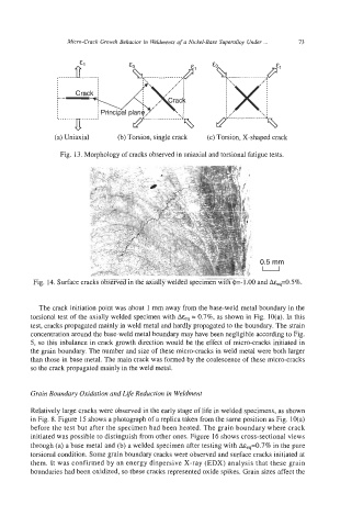
0.5 mm
U
Fig. 14. Surface cracks observed in the axially welded specimen with @=-l.OO and A%=0.5%.
The crack initiation point was about 1 mm away from the base-weld metal boundary in the
torsional test of the axially welded specimen with A&q = 0.7%, as shown in Fig. 10(a). In this
test, cracks propagated mainly in weld metal and hardly propagated to the boundary. The strain
concentration around the base-weld metal boundary may have been negligible according to Fig.
5, so this inbalance in crack growth direction would be the effect of micro-cracks initiated in
the grain boundary. The number and size of these micro-cracks in weld metal were both larger
than those in base metal. The main crack was formed by the coalescence of these micro-cracks
so the crack propagated mainly in the weld metal.
Grain Boundary Oxidation and Life Reduction in Weldment
Relatively large cracks were observed in the early stage of life in welded specimens, as shown
in Fig. 8. Figure 15 shows a photograph of a replica taken from the same position as Fig. 10(a)
before the test but after the specimen had been heated. The grain boundary where crack
initiated was possible to distinguish from other ones. Figure 16 shows cross-sectional views
through (a) a base metal and (b) a welded specimen after testing with A&,,=0.7% in the pure
torsional condition. Some grain boundary cracks were observed and surface cracks initiated at
them. It was confirmed by an energy dispersive X-ray (EDX) analysis that these grain
boundaries had been oxidized, so these cracks represented oxide spikes. Grain sizes affect the