
Page 283 - Biofuels Refining and Performance
P. 283
262 Chapter Nine
initial concentration of the bulk fluid and a concentration gradient is
formed, resulting in a loss of electrode potential. Although several
processes contribute to concentration polarization, at practical current
densities, slow transport of reactants and products to and from the elec-
trochemical reaction site is a major contributor to concentration polar-
ization. The effect of polarization is to shift the potential of the electrode:
For the anode,
V anode E anode |h anode |
and for the cathode,
E |h |
V cathode cathode cathode
The net result of current flow in a fuel cell is to increase the anode
potential and to decrease the cathode potential. This reduces the cell
voltage. The cell voltage includes the contribution of the anode and
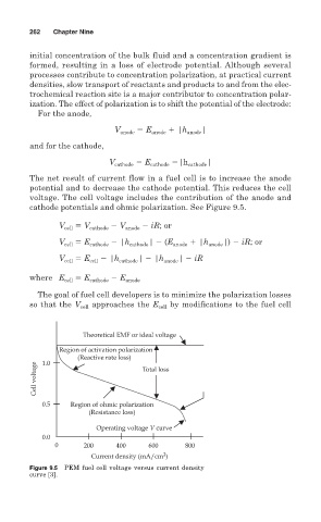
cathode potentials and ohmic polarization. See Figure 9.5.
V cell V cathode V anode iR; or
V cell E cathode |h cathode | (E anode |h anode |) iR; or
E |h | |h | iR
V cell cell cathode anode
where E cell E cathode E anode
The goal of fuel cell developers is to minimize the polarization losses
so that the V cell approaches the E cell by modifications to the fuel cell
Theoretical EMF or ideal voltage
Region of activation polarization
(Reactive rate loss)
1.0
Cell voltage Total loss
0.5 Region of ohmic polarization
(Resistance loss)
Operating voltage V curve
0.0
0 200 400 600 800
2
Current density (mA/cm )
Figure 9.5 PEM fuel cell voltage versus current density
curve [3].