
Page 240 - Biomedical Engineering and Design Handbook Volume 1, Fundamentals
P. 240
BIODYNAMICS: A LAGRANGIAN APPROACH 217
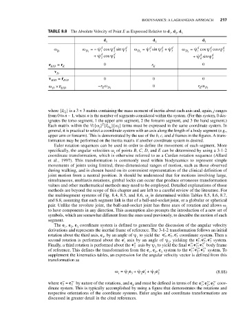
TABLE 8.8 The Absolute Velocity of Point E as Expressed Relative to d , d , d
1 2 3
d d d
1 2 3
d
d
d
d
d
d
ω ω =− ψ cos ψ sin ψ d ω = ψ sin ψ + ψ d ω = ψ cos ψ cos ψ d
D D 1 1 2 3 D 2 1 2 3 D 3 1 2 3
d d d d
+ ψ cos ψ 3 + ψ sin ψ 3
2
2
r = r 0 r 0
/
ED E E
v
D
v = r 0 0 0
/
/
ED E D
ω × r E D −r ω D 3 0 r ω D 1
E
E
D
/
where {I G j } is a 3 × 3 matrix containing the mass moment of inertia about each axis and, again, j ranges
from 0 to n − 1, where n is the number of segments considered within the system. (For this system, 0 des-
ignates the torso segment, 1 the upper arm segment, 2 the forearm segment, and 3 the hand segment.)
T
i
i
Each matrix within the 1 /2{ω } {I G n }{ω } terms must be expressed in the same coordinate system. In
general, it is practical to select a coordinate system with an axis along the length of a body segment (e.g.,
upper arm or forearm). This is demonstrated by the use of the b, c, and d frames in the figures. A trans-
formation may be performed on the inertia matrix if another coordinate system is desired.
Euler rotation sequences can be used in order to define the movement of each segment. More
specifically, the angular velocities ω of points B, C, D, and E can be determined by using a 3-1-2
i
coordinate transformation, which is otherwise referred to as a Cardan rotation sequence (Allard
et al., 1997). This transformation is commonly used within biodynamics to represent simple
movements of joints using limited, three-dimensional ranges of motion, such as those observed
during walking, and is chosen based on its convenient representation of the clinical definition of
joint motion from a neutral position. It should be understood that for motions involving large,
simultaneous, multiaxis rotations, gimbal locks can occur that produce erroneous transformation
values and other mathematical methods may need to be employed. Detailed explanations of those
methods are beyond the scope of this chapter and are left to a careful review of the literature. For
the multisegment systems of Fig. 8.4, 8.5, and 8.6, ω is determined within Tables 8.5, 8.6, 8.7,
i
and 8.8, assuming that each segment link is that of a ball-and-socket joint, or a globular or spherical
pair. Unlike the revolute joint, the ball-and-socket joint has three axes of rotation and allows ω i
to have components in any direction. This assumption also prompts the introduction of a new set of
symbols, which are somewhat different from the ones used previously, to describe the motion of each
segment.
The e , e , e coordinate system is defined to generalize the discussion of the angular velocity
2
1
3
derivations and represents the inertial frame of reference. The 3-1-2 transformation follows an initial
′
,
rotation about the third axis, e , by an angle of ψ to yield the ′ ee e , ′ 3 coordinate system. Then a
1
2
1
3
second rotation is performed about the e′ axis by an angle of ψ , yielding the ′′ ′′ ′′ e ,, 2 3 system.
ee
1
2
1
Finally, a third rotation is performed about the ′′ e 2 axis by ψ to yield the final ′′′ ′′′ ′′′ body frame
ee e ,
,
2
3
1
3
of reference. This defines the transformation from the e , e , e system to the ′′′ ′′′ ′′′ system. To
,
ee e ,
1
3
2
2
1
3
supplement the kinematics tables, an expression for the angular velocity vector is defined from this
transformation as
ψ
ψ ′ + e
ω = e + e ψ ′′ (8.88)
i
3 2
21
13
where ′′ = ′′′ by nature of the rotations, and e and must be defined in terms of the ′′′ ′′′ ′′′ coor-
e
e
ee e ,
,
3
2
2
2
1
3
dinate system. This is typically accomplished by using a figure that demonstrates the rotations and
respective orientations of the coordinate systems. Euler angles and coordinate transformations are
discussed in greater detail in the cited references.