
Page 235 - Biomedical Engineering and Design Handbook Volume 1, Fundamentals
P. 235
212 BIOMECHANICS OF THE HUMAN BODY
8.5.1 Single Rigid Body with a Single Degree of Freedom
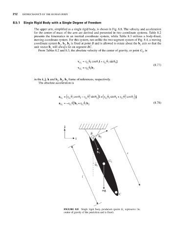
The upper arm, simplified as a single rigid body, is shown in Fig. 8.8. The velocity and acceleration
for the center of mass of the arm are derived and presented in two coordinate systems. Table 8.2
presents the kinematics in an inertial coordinate system, while Table 8.3 utilizes a body-fixed,
moving coordinate system. For this system, not unlike the two-segment system of Fig. 8.4, a moving
coordinate system b , b , b is fixed at point B and is allowed to rotate about the b axis so that the
3
1
3
2
unit vector b will always lie on segment BC.
1
From Tables 8.2 and 8.3, the absolute velocity of the center of gravity, or point G , is
1
v = r θ cos θ i + r θ sin θ j
G 1 G 1 1 1 G 1 1 1 (8.77)
v = r θ b
G 1 G 1 13
in the i, j, k and b , b , b frame of references, respectively.
1 2 3
The absolute acceleration is
2
1)
2
θ
θ cos
a = r ( θ − r θ sin θ 1) +i ( r θ sinθ + r θ cos θ j
G 1 G 1 1 1 G 1 1 G 1 1 1 G 1 1
2
a G 1 =−r G 1 θ b + r G 1 θ b (8.78)
1 2
1 1
j
B
b 2
i
b 1 r
G 1
θ 1
l
mg
C
FIGURE 8.8 Single rigid body pendulum (point G represents the
1
center of gravity of the pendulum and is fixed).