
Page 234 - Biomedical Engineering and Design Handbook Volume 1, Fundamentals
P. 234
BIODYNAMICS: A LAGRANGIAN APPROACH 211
TABLE 8.1 Blank Kinematics Table
i j k
ω B
(a) Angular velocity of coordinate system with its
origin at B
α =
ω
B B
(b) Angular acceleration of coordinate system with its
origin at B
r
P/B
(c) Relative displacement of point P with respect to B
V
B
(d) Base velocity of origin B
v = r
/
/
PB PB
(e) Relative velocity of point P with respect to B
ω × r
B P/B
( f ) Transport velocity
a
B
(g) Base acceleration
a = r
/
/
PB PB
(h) Relative acceleration
α × r
B P/B
(i) Acceleration due to angular acceleration of rotation
frame
ω × (ω × r )
B B P/B
(j) Centripetal acceleration
2ω × r P B
B
/
(k) Coriolis acceleration
2. Middle section (rows d, e, and f): Summed to yield
the absolute velocity (velocity with respect to an
inertial frame of reference) of point P. j
3. Bottom section (rows g, h, i, j, and k): Summed to
yield the absolute acceleration (acceleration with
respect to an inertial frame of reference) of point P.
All terms in the first column are vectors and are resolved P
rd
nd
into their vector components in the 2 ,3 , and 4 th
columns and the unit vectors of the selected coordinate
system are written at the top of the columns.
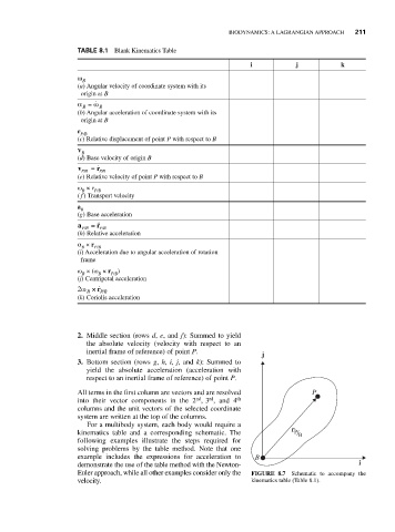
For a multibody system, each body would require a
kinematics table and a corresponding schematic. The r P / B
following examples illustrate the steps required for
solving problems by the table method. Note that one
example includes the expressions for acceleration to B
demonstrate the use of the table method with the Newton- i
Euler approach, while all other examples consider only the FIGURE 8.7 Schematic to accompany the
velocity. kinematics table (Table 8.1).