Page 230 - Biomedical Engineering and Design Handbook Volume 1, Fundamentals
P. 230

BIODYNAMICS: A LAGRANGIAN APPROACH  207

                          So that
                                                         ⎛
                                                       d ∂ ⎞  =  1  ml θ
                                                          L
                                                                   2
                                                           1
                                                         ⎜
                                                       dt ∂ ⎠ ⎟  3  13 1                     (8.55)
                                                         ⎝ θ
                                                           1
                          The appropriate terms can be substituted into Lagrange’s equation (8.11) to give
                                     1  2     1  2  2        1      2      1
                                      ml θ −  ml Ω sin θ cos θ −  ml l Ω coosθ + mgl 3 sinθ =  0  (8.56)
                                               1 3
                                                      1
                                                               1 2 3
                                                                                   1
                                                                        1
                                                                             1
                                                          1
                                       13 1
                                     3      3                2             2
                          since there are no externally applied torques acting on the system in the θ direction. The resulting
                                                                                1
                          equation of motion for the one-segment system is solved as
                                                2  θ cos θ −  3 l 2  Ω cos θ +  3 g  sin θ = 0  (8.57)
                                                               2
                                           θ − Ω sin
                                                                               0
                                                        1
                                                    1
                                            1
                                                           2 l 3    1  2 l 3  1
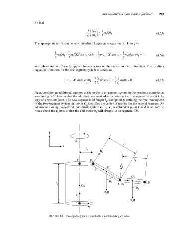
                          Next, consider an additional segment added to the two-segment system in the previous example, as
                          seen in Fig. 8.5. Assume that the additional segment added adjoins to the first segment at point C by
                          way of a revolute joint. The new segment is of length l , with point D defining the free-moving end
                                                                 4
                          of the two-segment system and point G identifies the center of gravity for the second segment. An
                                                      2
                          additional moving body-fixed, coordinate system c , c , c is defined at point C and is allowed to
                                                               1  2  3
                          rotate about the c axis so that the unit vector c will always lie on segment CD.
                                      3                     1
                                  j
                                                Ω
                                                                           l 3
                                         i
                                                      l 2     b 2
                                                 F      B                        l 4
                                                                         c 2
                                                                  G 1
                                                           b 1
                                                                               G 2
                                                                   θ
                                     l 1                            1   C  c 1           D
                                                   G 0                            θ
                                                                m g                2
                                                                 1
                                                a 2
                                                                               m g
                                                                                2
                                                A
                                                       a 1

                                 FIGURE 8.5 Two rigid segments connected to a nontranslating cylinder.
   225   226   227   228   229   230   231   232   233   234   235