
Page 233 - Biomedical Engineering and Design Handbook Volume 1, Fundamentals
P. 233
210 BIOMECHANICS OF THE HUMAN BODY
j
Ω
l 3
i
l 2
b 2
F B l 4
l 5
c 2 d
b 1 G 1 2
G 2 G 3
θ 1 E
l 1 G 0 C c 1 D d 1
g θ 2 θ 3
m 1
a 2
m 2 g m g
3
A
a 1
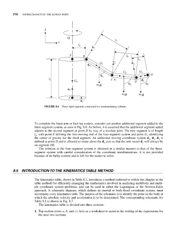
FIGURE 8.6 Three rigid segments connected to a nontranslating cylinder.
To complete the hand-arm or foot-leg system, consider yet another additional segment added to the
three-segment system, as seen in Fig. 8.6. As before, it is assumed that the additional segment added
adjoins to the second segment at point D by way of a revolute joint. The new segment is of length
l , with point E defining the free-moving end of the four-segment system and point G identifying
5
3
the center of gravity for the third segment. An additional moving coordinate system d , d , d is
2
3
1
defined at point D and is allowed to rotate about the d axis so that the unit vector d will always lie
3
1
on segment DE.
The solution to the four-segment system is obtained in a similar manner to that of the three-
segment system with careful consideration of the coordinate transformations. It is not provided
because of its bulky content and is left for the reader to solve.
8.5 INTRODUCTION TO THE KINEMATICS TABLE METHOD
The kinematics table, shown in Table 8.1, introduces a method (referred to within this chapter as the
table method) for efficiently managing the mathematics involved in analyzing multibody and multi-
ple coordinate system problems, and can be used in either the Lagrangian or the Newton-Euler
approach. A schematic diagram, which defines an inertial or body-fixed coordinate system, must
accompany every kinematics table. The purpose of the schematic is to identify the point on the body at
which the absolute velocity and acceleration is to be determined. The corresponding schematic for
Table 8.1 is shown in Fig. 8.7.
The kinematics table is divided into three sections.
1. Top section (rows a, b, and c): Acts as a worksheet to assist in the writing of the expressions for
the next two sections.