
Page 50 - Biomedical Engineering and Design Handbook Volume 1, Fundamentals
P. 50
MODELING OF BIOMEDICAL SYSTEMS 27
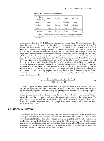
TABLE 1.1 Fuzzy-rules Lookup Table
Force
Small Medium Large Very large
Stiffness
Small No cut Small Medium Large
Medium No cut No cut Small Medium
Large No cut No cut No cut Small
Very large No cut No cut No cut No cut
The force subdomains are in the horizontal column and the stiffness domains
are described in the vertical column. The corresponding output subdomain is given
in the cells.
developed a lookup table (IF-THEN rules) to compute the cutting depth. Table 1.1 shows the lookup
table. For instance, if the normalized force is 0.4, the membership values are (0, 0.5, 0.3, 0). The
membership value for small is zero, for medium is 0.5, for large is 0.3, and zero for very large. If the
normalized stiffness at the cutting location is 0.32, the membership values for stiffness are (0.4, 0.8,
0.4, 0). The stiffness membership value is 0.4 for small, 0.8 for medium, 0.4 for large, and 0 for very
large. The contribution to the output domain small cut is calculated from the lookup table by adding
all the possibilities for small cut. Small cut is possible if the force is medium (0.5) and the stiffness
is small (0.4) which results in 0.4 times 0.5 which is 0.2; additional possibility is if force is large
(0.3) and stiffness is medium (0.8) which results in 0.3 × 0.8 = 0.24 for small cut. Another possibil-
ity is if force is very large (0) and stiffness is large (0.4) which results in 0. Now, the membership
value for the output subdomain small cut is calculated by adding all these possibilities: 0.2 + 0.24 +
0 = 0.44. Similar calculation for medium cut results in 0.3 × 0.4 = 0.12. The membership value for
no cut results in 0.5 (0.8 + 0.4) + 0.3 × 0.4 = 72. The output membership values for this example are
(0.72, 0.44, 0.12, 0). The fuzzy output of the cutting depth is then defuzzified using the centoid
defuzzification scheme to calculate a crisp value for the cutting depth. In the above example, the
crisp value is calculated as
.
.
1
0 72 ×+ 0 44 × 2 + 0 12 × 3 + 0 × 4
.
C = (1.69)
072 + 044 + 012 + 0
.
.
.
At each epoch, the force exerted by the user on the pseudo cutting tool is measured, fuzzified,
and the cutting depth is calculated. The virtual cutting tool is then advanced to the depth computed
by the fuzzy logic system. The node(s) along the cutting path are released, and the display is updated
with cut view. Then, the user’s input force exerted on the pseudo-cutting tool is measured, defuzzi-
fied, and the cutting is performed by advancing the tool to the new location by the amount of cutting
depth. The procedure is repeated as long as the pseudo-cutting tool is in the cutting space. The
procedure is continued until the pseudo-cutting tool is withdrawn out of the virtual tissue space.
Figure 1.17 provides a demonstration of fuzzy-logic-based tissue cutting in VR environment using
two-dimensional models.
1.7 MODEL VALIDATION
This chapter discussed the art of modeling with few examples. Regardless of the type of model
developed, a mathematical model should be validated with experimental results. Validation becomes
very important in the black box type of models such as the neural network models. Moreover, the
model results are valid only to certain regimes where the model assumptions are valid. Sometimes,
any model can be fit to a particular data by adjusting the parameter values. Moreover, the techniques
of parameter estimation were not presented in this chapter. In addition, the presentation was limited
to lumped parameter analysis or macroscopic modeling.