Page 283 - Biomedical Engineering and Design Handbook Volume 2, Applications
P. 283

INSTRUMENTATION DESIGN FOR ULTRASONIC IMAGING  261


                                 20
                                        Summing          Delay            Wavefronts
                               Depth along transducer, mm  0  Σ
                                                         lines
                                        state
                                                                          before correction
                                 10


                                –10

                                                              elements
                                              Wavefront       Array
                                –20
                                              after correction

                                     –40   –30    –20    –10    0     10     20     30    40
                                                             Depth, mm
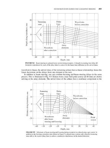
                             FIGURE 9.8  Beam steering in a phased array system during reception. A linearly increasing time delay dif-
                             ferential is introduced for each of the delay lines to correct for the linear time difference in the arrival times.

                          wavefront is linear, the arrival times of the remaining echoes have a linear relationship; hence the
                          linear decrement on the delays from one element to the next.
                            In addition to beam steering, one can combine focusing and beam-steering delays in the same
                          process. This is illustrated in Fig. 9.9. Echoes from a near field point source (at 40 mm) are shown
                          arriving at the array elements. The arrival times of the echoes have a nonlinear component so the


                                 20
                                          Summing        Delay          Wavefronts
                               Distance along transducer, mm  0  Σ      before correction
                                                         lines
                                          stage
                                 10


                                 –10

                                              Wavefronts       Array                    Point
                                 –20                           elements
                                              after beam                                source
                                              steering and focusing
                                      –40   –30   –20    –10    0     10     20    30    40
                                                             Depth, mm
                              FIGURE 9.9 Schematic of beam steering and focusing during reception in a phased array type system. In
                              addition to the focusing correction (also shown in Figure 3), phased array systems add a linearly increasing
                              time shift to the receive delay lines to achieve constructive interference in the desired direction.
   278   279   280   281   282   283   284   285   286   287   288