
Page 279 - Biomedical Engineering and Design Handbook Volume 2, Applications
P. 279
INSTRUMENTATION DESIGN FOR ULTRASONIC IMAGING 257
x10 4
2.5 2
Acoustic pressure (arbitrary units) 1.5 1
0.5
0
20
10 200
0 150
100
Range, mm –10 50
–20 0 Array face, mm
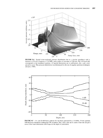
FIGURE 9.4 Spatial cross-sectional pressure distribution due to a circular transducer with a
diameter of 20 mm, frequency of 3.0 MHz, and a radius of curvature of 100 mm. The left-hand side
corresponds to the transducer aperture. All spatial dimensions are in millimeters, the x and y axes
are not to scale. This pressure distribution was determined by the use of angular spectrum techniques
(Schafer, 1989).
60
40
Depth along transducer, mm –20 0 6 dB
20
–40 20 dB
–60
0 50 100 150 200
Depth, mm
FIGURE 9.5 A 6- and 20-dB beam contours for the beam generated by a 3.0-MHz, 19-mm aperture,
100-mm focus transducer undergoing CW excitation. The x and y axes are to scale so that one can get a
sense of the beam dimensions with respect to the depth of penetration.