
Page 274 - Biomedical Engineering and Design Handbook Volume 2, Applications
P. 274
252 DIAGNOSTIC EQUIPMENT DESIGN
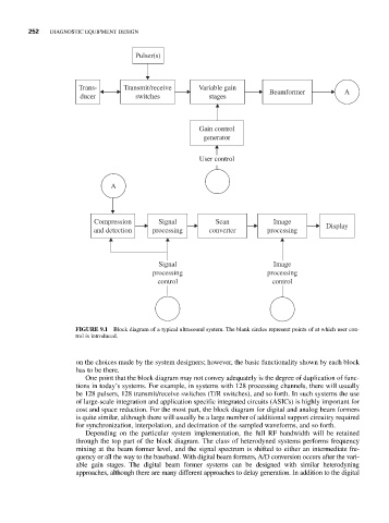
Pulser(s)
Trans- Transmit/receive Variable gain Beamformer A
ducer switches stages
Gain control
generator
User control
A
Compression Signal Scan Image
Display
and detection processing converter processing
Signal Image
processing processing
control control
FIGURE 9.1 Block diagram of a typical ultrasound system. The blank circles represent points of at which user con-
trol is introduced.
on the choices made by the system designers; however, the basic functionality shown by each block
has to be there.
One point that the block diagram may not convey adequately is the degree of duplication of func-
tions in today’s systems. For example, in systems with 128 processing channels, there will usually
be 128 pulsers, 128 transmit/receive switches (T/R switches), and so forth. In such systems the use
of large-scale integration and application specific integrated circuits (ASICs) is highly important for
cost and space reduction. For the most part, the block diagram for digital and analog beam formers
is quite similar, although there will usually be a large number of additional support circuitry required
for synchronization, interpolation, and decimation of the sampled waveforms, and so forth.
Depending on the particular system implementation, the full RF bandwidth will be retained
through the top part of the block diagram. The class of heterodyned systems performs frequency
mixing at the beam former level, and the signal spectrum is shifted to either an intermediate fre-
quency or all the way to the baseband. With digital beam formers, A/D conversion occurs after the vari-
able gain stages. The digital beam former systems can be designed with similar heterodyning
approaches, although there are many different approaches to delay generation. In addition to the digital