
Page 277 - Biomedical Engineering and Design Handbook Volume 2, Applications
P. 277
INSTRUMENTATION DESIGN FOR ULTRASONIC IMAGING 255
20
Summing Delay Wavefronts
Distance along transducer, mm 0 Σ Point
lines
before correction
stage
10
source
–10
after correction
elements
–20 Wavefronts Transducer
–40 –30 –20 –10 0 10 20 30 40
Depth, mm
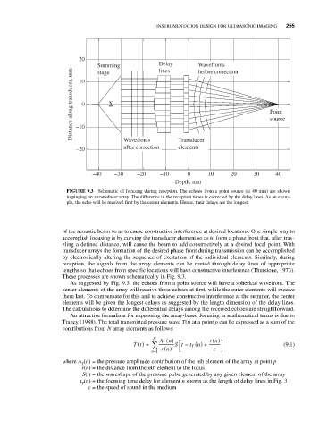
FIGURE 9.3 Schematic of focusing during reception. The echoes from a point source (at 40 mm) are shown
impinging on a transducer array. The difference in the reception times is corrected by the delay lines. As an exam-
ple, the echo will be received first by the center elements. Hence, their delays are the longest.
of the acoustic beam so as to cause constructive interference at desired locations. One simple way to
accomplish focusing is by curving the transducer element so as to form a phase front that, after trav-
eling a defined distance, will cause the beam to add constructively at a desired focal point. With
transducer arrays the formation of the desired phase front during transmission can be accomplished
by electronically altering the sequence of excitation of the individual elements. Similarly, during
reception, the signals from the array elements can be routed through delay lines of appropriate
lengths so that echoes from specific locations will have constructive interference (Thurstone, 1973).
These processes are shown schematically in Fig. 9.3.
As suggested by Fig. 9.3, the echoes from a point source will have a spherical wavefront. The
center elements of the array will receive these echoes at first, while the outer elements will receive
them last. To compensate for this and to achieve constructive interference at the summer, the center
elements will be given the longest delays as suggested by the length dimension of the delay lines.
The calculations to determine the differential delays among the received echoes are straightforward.
An attractive formalism for expressing the array-based focusing in mathematical terms is due to
Trahey (1988). The total transmitted pressure wave T(t) at a point p can be expressed as a sum of the
contributions from N array elements as follows:
N An ( ) rn ( )
⎡
Tt ( ) = ∑ T St − t T ( n) + ⎤ (9.1)
⎣ ⎢
n=1 rn ( ) c ⎦ ⎥
where A (n) = the pressure amplitude contribution of the nth element of the array at point p
T
r(n) = the distance from the nth element to the focus
S(t) = the waveshape of the pressure pulse generated by any given element of the array
t (n) = the focusing time delay for element n shown as the length of delay lines in Fig. 3
T
c = the speed of sound in the medium