
Page 282 - Biomedical Engineering and Design Handbook Volume 2, Applications
P. 282
260 DIAGNOSTIC EQUIPMENT DESIGN
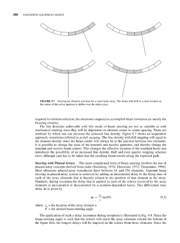
FIGURE 9.7 Steering by element selection for a curvilinear array. The beam will shift to a new location as
the center of the active aperture is shifter over the entire array.
required for element selection, the electronics required to accomplish beam formation are merely the
focusing circuitry.
The line densities achievable with this mode of beam steering are not as variable as with
mechanical steering since they will be dependent on element center-to-center spacing. There are
methods by which one can increase the achieved line density. Figure 9.7 shows an acquisition
approach, sometimes referred to as full stepping. The line density with full stepping will equal to
the element density since the beam center will always be at the junction between two elements.
It is possible to change the sizes of the transmit and receive apertures, and thereby change the
transmit and receive beam centers. This changes the effective location of the resultant beam and
introduces the possibility of an increased line density. Half and even quarter stepping schemes
exist, although care has to be taken that the resulting beam travels along the expected path.
Steering with Phased Arrays. The most complicated form of beam steering involves the use of
phased-array concepts derived from radar (Steinberg, 1976; Thurstone, 1973; Thomenius, 1996).
Most ultrasonic phased-array transducers have between 64 and 256 elements. Transmit beam
steering in phased-array system is achieved by adding an incremental delay to the firing time of
each of the array elements that is linearly related to the position of that element in the array.
Similarly, during reception the delay that is applied to each of the echoes received by the array
elements is incremented or decremented by a position-dependent factor. This differential time
delay Δt is given by
Δt = x n tan ( ) θ (9.3)
c
where x = the location of the array element n
n
θ= the desired beam-steering angle
The application of such a delay increment during reception is illustrated in Fig. 9.8. Since the
beam-steering angle is such that the echoes will reach the array elements toward the bottom of
the figure first, the longest delays will be imposed on the echoes from those elements. Since the