
Page 429 - Biomedical Engineering and Design Handbook Volume 2, Applications
P. 429
COMPUTER-INTEGRATED SURGERY AND MEDICAL ROBOTICS 407
25
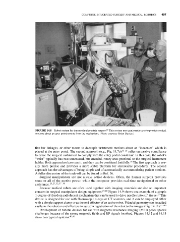
FIGURE 14.8 Robot system for transurethral prostate surgery. This system uses goniometer arcs to provide conical
motions about an apex point remote from the mechanism. (Photo courtesy Brian Davies.)
five-bar linkages, or other means to decouple instrument motions about an “isocenter” which is
placed at the entry portal. The second approach (e.g., Fig. 14.7a) 33–35 relies on passive compliance
to cause the surgical instrument to comply with the entry portal constraint. In this case, the robot’s
“wrist” typically has two unactuated, but encoded, rotary axes proximal to the surgical instrument
36
holder. Both approaches have merit, and they can be combined fruitfully. The first approach is usu-
ally more precise and provides a more stable platform for stereotactic procedures. The second
approach has the advantages of being simple and of automatically accommodating patient motions.
A fuller discussion of the trade-off can be found in Ref. 36.
Surgical manipulators are not always active devices. Often, the human surgeon provides
some or all of the motive power, while the computer provides real-time navigational or other
assistance. 25,27,32,37–39
Because medical robots are often used together with imaging, materials are also an important
concern in surgical manipulator design equipment. 27,40 Figure 14.9 shows one example of a simple
27
1-degree-of-freedom radiolucent mechanism that can be used to drive needles into soft tissue. This
device is designed for use with fluoroscopic x-rays or CT scanners, and it can be employed either
with a simple support clamp or as the end effector of an active robot. Fiducial geometry can be added
easily to the robot or end effectors to assist in registration of the robot to the images (Fig. 14.11). 41–45
Development of robotic devices for use with magnetic resonance imaging (MRI) poses special
challenges because of the strong magnetic fields and RF signals involved. Figures 14.12 and 14.13
show two typical systems. 40,46