
Page 231 - Biomimetics : Biologically Inspired Technologies
P. 231
Bar-Cohen : Biomimetics: Biologically Inspired Technologies DK3163_c007 Final Proof page 217 21.9.2005 11:41am
Bio-Nanorobotics 217
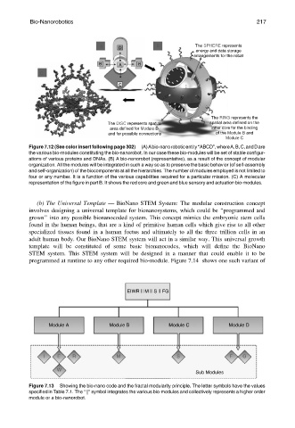
A D B The SPHERE represents
energy and data storage
arrangements for the robat
B A B
C
C
The RING represents the
The DISC represents spatial spatial area defined on the
area defined for Module D inner core for the binding
and for possible connections of the Module B and
Module C
Figure 7.12 (See color insert following page 302) (A)Abio-nanoroboticentity‘‘ABCD’’,whereA,B,C,andDare
the various bio-modules constituting the bio-nanorobot. In our case these bio-modules will be set of stable configur-
ations of various proteins and DNAs. (B) A bio-nanorobot (representative), as a result of the concept of modular
organization. All the modules will be integrated in such a way so as to preserve the basic behavior (of self-assembly
and self-organization) of the biocomponents at all the hierarchies. The number of modules employed is not limited to
four or any number. It is a function of the various capabilities required for a particular mission. (C) A molecular
representation of the figure in part B. It shows the red core and green and blue sensory and actuation bio-modules.
(b) The Universal Template — BioNano STEM System: The modular construction concept
involves designing a universal template for bionanosystems, which could be ‘‘programmed and
grown’’ into any possible bionanocoded system. This concept mimics the embryonic stem cells
found in the human beings, that are a kind of primitive human cells which give rise to all other
specialized tissues found in a human foetus and ultimately to all the three trillion cells in an
adult human body. Our BioNano STEM system will act in a similar way. This universal growth
template will be constituted of some basic bionanocodes, which will define the BioNano
STEM system. This STEM system will be designed in a manner that could enable it to be
programmed at runtime to any other required bio-module. Figure 7.14 shows one such variant of
EIWR || M || S || FG
Module A Module B Module C Module D
I E R M S F G
W
Sub Modules
Figure 7.13 Showing the bio-nano code and the fractal modularity principle. The letter symbols have the values
specified in Table 7.1. The ‘‘k’’ symbol integrates the various bio-modules and collectively represents a higher order
module or a bio-nanorobot.