
Page 226 - Biomimetics : Biologically Inspired Technologies
P. 226
Bar-Cohen : Biomimetics: Biologically Inspired Technologies DK3163_c007 Final Proof page 212 21.9.2005 11:41am
212 Biomimetics: Biologically Inspired Technologies
(a) (b) (c)
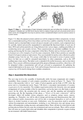
Figure 7.7 (Step 1) Understanding of basic biological components and controlling their functions as robotic
components. Examples are: (a) DNA which may be used in a variety of ways such as a structural element and a
power source; (b) hemagglutinin virus may be used as a motor; (c) bacteriorhodopsin could be used as a sensor or
a power source.
Figure 7.7). Since the planned systems and devices will be composed of these components, we must
have a sound understanding of how these behave and how they could be controlled. From the simple
elements such as structural links to more advanced concepts such as motors, each component must
be carefully studied and possibly manipulated to understand the functional limits of each one of
them. DNA and carbon nanotubes are being fabricated into various shapes, enabling possibilities of
constructing newer and complex devices. These nanostructures are potential candidates for inte-
grating and housing the bio-nano components within them. Proteins such as rhodopsin and bacter-
iorhodopsin are a few examples of such bio-nano components. Both of these proteins are naturally
found in biological systems as light sensors. They can essentially be used as solar collectors to gather
abundant energy from the sun. This energy could either be harvested (in terms of proton motive
force) for later use or could be consumed immediately by other components, such as the ATP
synthase nano rotary motor. The initial work is intended to be on the biosensors, such as heat shock
factor. These sensors will form an integral part of the proposed bionano assemblies, where these will
be integrated within a nanostructure and will get activated as programmed, for gathering the
required information at the nano-scale. Tools and techniques from molecular modeling and protein
engineering will be used to design these modular components.
Step 2: Assembled Bio-Nanorobots
The next step involves the assembly of functionally stable bio-nano components into complex
assemblies. Some examples of such complex assemblies are shown in Figure 7.8. Figure 7.8A
shows a bio-nanorobot with its ‘‘feet’’ made of helical peptides and its body of CNT, while the
power unit is a biomolecular motor. Figure 7.8B shows a conceptual representation of modular
organization of a bio-nanorobot. The modular organization defines the hierarchy rules and spatial
arrangements of various modules of the bio-nanorobots, such as the inner core (the brain or energy
source for the robot), the actuation unit, the sensory unit, and the signaling and information
processing unit. By the beginning of this phase, a ‘‘library of bio-nano components’’ will be
developed, which will include various categories, such as actuation, energy source, sensory,
signaling, etc. Thereafter, one will be able to design and develop such bionanosystems that will
have enhanced mobile characteristics and will be able to transport themselves as well as other
objects to desired locations at nano-scale. Furthermore, some bio-nanorobots need to assemble
various biocomponents and nanostructures, including in situ fabrication sites and storage areas;
others will manipulate existing structures and maintain them. There will also be robots that not only
perform physical labor, but also sense the environment and react accordingly. There will be systems
that will sense an oxygen deprivation and stimulate other components to generate oxygen creating
an environment with stable homoeostasis.