
Page 225 - Biomimetics : Biologically Inspired Technologies
P. 225
Bar-Cohen : Biomimetics: Biologically Inspired Technologies DK3163_c007 Final Proof page 211 21.9.2005 11:41am
Bio-Nanorobotics 211
this approach is the use of zinc to control F 1 -ATPase, which is able to rotate a nanopropeller in the
presence of ATP. A computational algorithm (Hellinga and Richards, 1991) was used to determine
the mutations necessary to engineer an allosteric zinc-binding site into the F 1 -ATPase using site-
directed mutagenesis. The mutant F 1 -ATPase would rotate an actin filament in the presence of ATP
with average torque of 34 pNm. This rotation could be stopped with the addition of zinc, and
restored with the addition of a chelator to remove the zinc from the allosteric binding site (Liu et al.,
2002). This type of approach can be used for the improvement of other protein-based nano
components.
These biocomponents seem to beavery logical choicefor designingnanorobots.Inaddition, since
some of the core applications of nanorobots are in the medical field, using biocomponents for these
applications seems to be a good choice as they both offer efficiency and variety of functionality. This
idea is clearly inspired by nature’s construction of complex organisms such as bacteria and viruses
which arecapable ofmovement,sensing, and organizedcontrol. Hence, ourscope wouldbelimitedto
the usage of these biocomponents in the construction of bio-nanorobotics. A roadmap is proposed
which details the main steps towards the design and development of bio-nanorobots.
7.3.1 The Roadmap
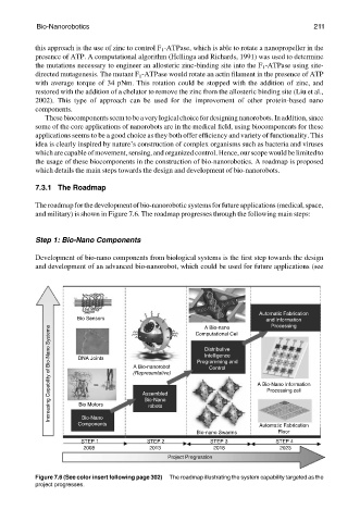
The roadmap for thedevelopment of bio-nanorobotic systems for future applications (medical, space,
and military) is shown in Figure 7.6. The roadmap progresses through the following main steps:
Step 1: Bio-Nano Components
Development of bio-nano components from biological systems is the first step towards the design
and development of an advanced bio-nanorobot, which could be used for future applications (see
Automatic Fabrication
Bio Sensors Computational Cell and Information
Processing
Increasing Capability of Bio-Nano Systems DNA Joints (Representative) Programming and A Bio-Nano Information
A Bio-nano
Distributive
Intelligence
A Bio-nanorobot
Control
Processing cell
Assembled
Bio Motors
robots
Bio-Nano
Components Bio-Nano
Automatic Fabrication
Bio-nano Swarms Floor
STEP 1 STEP 2 STEP 3 STEP 4
2008 2013 2018 2023
Project Progression
Figure 7.6 (See color insert following page 302) The roadmap illustrating the system capability targeted as the
project progresses.