Page 425 - Biomimetics : Biologically Inspired Technologies
P. 425

Bar-Cohen : Biomimetics: Biologically Inspired Technologies  DK3163_c016 Final Proof page 411 21.9.2005 11:49pm


                    Biomimetic and Biologically Inspired Control                                411


                                     2.5                     2.5
                                      2              Joint 1  2              Joint 2
                                    angle [rad]  1.5 1      angle [rad]  1.5 1

                                                             0.5
                                     0.5
                                      0                       0
                                                    Joint 2                 Joint 1
                                    −0.5                    −0.5
                                       0  0.1  0.2  0.3  0.4  0.5  0  0.1  0.2  0.3  0.4  0.5
                                               time (s)                time (s)
                                         Optimal and  semi-optimal  optimal and  semi-optimal
                                              joint angles            joint angles
                                     1.6                      2
                                     1.4  Joint 1
                                     1.2 1                    1        Joint 1
                                    velocity [rad/s]  0.8   velocity [rad/s]  −1 0
                                     0.6
                                     0.4
                                     0.2          Joint 2    −2         Joint 1
                                      0
                                    −0.2                     −3
                                       0  0.1  0.2  0.3  0.4  0.5  0  0.1  0.2  0.3  0.4  0.5
                                               time (s)                time (s)
                                         optimal and  semi-optimal  optimal and  semi-optimal
                                             joint velocities         joint velocities
                                      3                       3
                                              Joint 1         2
                                      2
                                                              1   Joint 1     Joint 2
                                    torque [Nm]  −1 0  Joint 2  torque [Nm]  0
                                      1
                                     −2                      −1
                                                             −2
                                     −3                      −3
                                       0  0.1  0.2  0.3  0.4  0.5  0  0.1  0.2  0.3  0.4  0.5
                                               time (s)                time (s)
                                         optimal and  semi-optimal  optimal and  semi-optimal
                                              joint torques           joint torques
                                      (a) The motion from S to E1  (b) The motion from S to E2
                                                       T2             T3
                                                 0.5           E2
                                                 0.4  E1
                                               y - position [m]  0.3  S

                                                 0.2
                                                       T1              T4
                                                 0.1         teaching information
                                                             start position
                                                             end position
                                                             optimal trajectory
                                                  0          semi-optimal trajectory
                                                   0  0.1  0.2  0.3  0.4  0.5
                                                         x - position [m]
                                                 (c) The trajectories in the task space
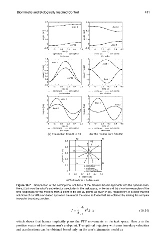
                    Figure 16.7  Comparison of the semioptimal solutions of the diffusion-based approach with the optimal ones.
                    Here, (c) shows the robot’s end-effector trajectories in the task space, while (a) and (b) show two examples of the
                    time responses for the motions from S point to E1 and E2 points as given in (c), respectively. It is clear that the
                    solutions of our diffusion-based approach are almost the same as those that are obtained by solving the complex
                    two-point boundary problem.
                                                          ð
                                                        1  T f  ::: T :::
                                                    J ¼     x x dt                           (16:14)
                                                        2  0

                    which shows that human implicitly plans the PTP movements in the task space. Here x is the
                    position vector of the human arm’s end-point. The optimal trajectory with zero boundary velocities
                    and accelerations can be obtained based only on the arm’s kinematic model as
   420   421   422   423   424   425   426   427   428   429   430