
Page 54 - Biosystems Engineering
P. 54
Biosystems Analysis and Optimization 35
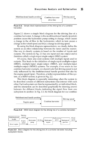
Multifunctional handle position Driving speed
Combine harvester
drive line
FIGURE 2.1 Simple block representation of the driving line of a combine
harvester.
Figure 2.1 shows a simple block diagram for the driving line of a
combine harvester. A change in the multifunctional handle (joystick)
position causes the hydrostatic pump setting to change, which causes
a change in the oil flow to the hydromotor, which in turn causes a
change in the wheel speed and thus a change in driving speed.
By using the block diagram representation, we clearly define the
system as an effect relationship between the inputs and the outputs.
One way to classify systems is based on the number of inputs and
outputs. The system in Fig. 2.1 has one input and one output and is
therefore called a single-input single-output (SISO) system.
Of course, there also exist systems with multiple inputs and/or
outputs. This leads to the definition of single-input multiple-output
(SIMO), multiple-input single-output (MISO), and multiple-input
multiple-output (MIMO) systems. For example, if we return to our
combine harvester example, we should note that driving speed is not
only influenced by the multifunctional handle position but also by
the engine speed (rpm). Therefore, a better representation of this sys-
tem, as a MISO system, is given in Fig. 2.2.
This block diagram is especially interesting when the system to
be described consists of different subsystems that interact with each
other. Each subsystem can then be represented by an individual block,
and the interaction can be described graphically by drawing arrows
between the different blocks indicating the signal flow from one
subsystem to another. In Fig. 2.3, the block diagram for our combine
Multifunctional handle position
Driving speed
Engine speed Combine harvester
FIGURE 2.2 MISO block diagram for the driving line of a combine harvester.
Steering
Multifunctional current
Hydromotor Wheel
handle speed speed
Engine Hydrostatic Oil flow Hydrostatic Mechanical
pump engine gear box
speed
Diesel engine
FIGURE 2.3 Block diagram for the driving line of a combine harvester including
subsystem blocks.