
Page 56 - Biosystems Engineering
P. 56
Biosystems Analysis and Optimization 37
the position of a damper shaft and the force exerted by the viscous
damper, between the position of a conductor moving in a magnetic
field, and the potential over this conductor, for example.
A capacitor or condenser can be seen as the counterpart of a sole-
noid, because the current i(t) through it is proportional to the time
derivative of the voltage v(t) over it:
it() = C dv t() (2.5)
dt
where C is the capacitance of the condenser. When the current i(t) is
again considered to be the input u(t) and the voltage v(t) to be the output,
Eq. (2.5) can be rewritten as follows to obtain the transfer function:
1
vt() = ∫ t it() or y t() = ∫ t u t() (2.6)
K
C 0 0
With this, the input–output relation is an integral function where the gain
K is equal to the inverse of the condenser capacity C. Other examples of
this integrator action can be found in the dynamic relation between the
oil flow to a hydraulic actuator and the shaft position, between the
water flow into a bath tub and the water level in the tub, and between
the energy production in a room and the temperature in the room.
More complex systems can often be described as a combination of the
higher mentioned building blocks by linking them in series or parallel.
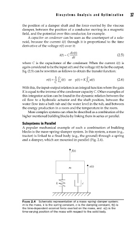
Subsystems in Parallel
A popular mechanical example of such a combination of building
blocks is the mass–spring–damper system. In this system, a mass (e.g.,
tractor) is linked to a fixed body (e.g., the ground) through a spring
and a damper, which are mounted in parallel (Fig. 2.4).
f(t)
m x(t)
k c
FIGURE 2.4 Schematic representation of a mass–spring–damper system;
m is the mass, k is the spring constant, c is the damping constant, f(t) is
the time-dependent external force exerted on the mass, and x(t) is the
time-varying position of the mass with respect to the solid body.