
Page 170 - Boiler_Operators_Handbook,_Second_Edition
P. 170
Refrigeration & AC 155
compressor cylinder through an intake valve or valves. the pressure of the gas at the outlet to overcome the force
My best description for the valves of a refrigeration of the spring on the valve and the discharge valve opens.
compressor is they look like popsicle sticks. They are For the remainder of the upward stroke gas is pushed
guided within the casting of a cylinder head and are ei- out of the cylinder into the discharge piping. The vol-
ther a spring themselves or guided by springs that gen- ume of gas delivered with each rotation of the shaft isn’t
tly push them toward the seat. The flow of gas pushes a function of the cylinder displacement because the gas
the valve away from the opening and, when flow stops, has to expand and compress. The amount of gas pushed
the spring force pushes the valve back onto its seat. As through the compressor is considerably less than the
the piston approaches the bottom of its stroke it slows volume displaced by the piston in the cylinder.
down then reverses due to the rotary motion of the pis- Small compressors are started under load. To allow
ton connecting rod at the crankshaft. Then, as the pis- larger compressors to get up to speed before starting to
ton rises in the cylinder, reducing the volume, the gas is pump refrigerant unloading systems are used. Unload-
compressed until it is at a pressure slightly higher than ing a cylinder is accomplished with a pin that pushes
up against each suction valve to hold it open. The pin
is connected to a small cylinder containing a spring as
shown in Figure 5-8. When the compressor is shut down
the springs push the pins up to hold the valves open. Af-
ter the compressor gets up to speed the oil pump builds
up pressure in the oil passages of the compressor and
the small unloader cylinders to force the pins down and
allow the suction valves to operate. You can tell when
the unloaders operate because there will be a significant
difference in the sound of the compressor as it comes up
to speed. The unloaders allow a compressor to be pow-
ered by a standard duty motor instead of a high torque
motor. Many modern compressors use a solenoid and
spring to control the pins electronically.
In addition to reducing startup torque unloaders
allow multiple cylinder compressors to handle varying
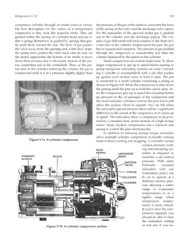
Figure 5-7a. 8-cylinder compressor
loads without starting and stopping. A controller senses
suction pressure, load-
ing and unloading cyl-
inders as required to
maintain a set suction
pressure. With older
hydraulic actuated
unloaders each one
(sometimes pairs) can
be set to operate at a
different suction pres-
sure allowing a wider
range of evaporator
temperatures or in a
tighter range when
temperature mainte-
nance is more critical.
If you’re near the com-
pressors regularly you
should be able to hear
the unloaders cutting
in and out. If you no-
Figure 5-7b. 8-cylinder compressor section