
Page 171 - Boiler_Operators_Handbook,_Second_Edition
P. 171
156 Boiler Operator’s Handbook
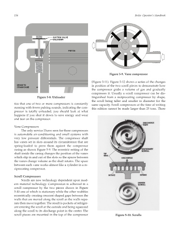
Figure 5-9. Vane compressor
(Figure 5-11). Figure 5-12 shows a series of the changes
in position of the two scroll pieces to demonstrate how
the compressor grabs a volume of gas and gradually
compresses it. Usually a scroll compressor can be dis-
Figure 5-8. Unloader tinguished from a reciprocating compressor by shape,
the scroll being taller and smaller in diameter for the
tice that one of two or more compressors is constantly
same capacity. Scroll compressors at the time of writing
running with fewer pulsing sounds, indicating the com-
this edition cannot be made larger than 25 tons. There
pressor is totally unloaded, you should look at what
happens if you shut it down to save energy and wear
and tear on the compressor.
Vane Compressors
The only service I have seen for these compressors
is automobile air-conditioning and small systems with
very low pressure differentials. The compressor shaft
has vanes set in slots around its circumference that are
spring-loaded to press them against the compressor
casing as shown Figure 5-9. The eccentric setting of the
shaft inside the casing changes the position of the vanes
which slip in and out of the slots so the spaces between
the vanes change volume as the shaft rotates. The space
between each vane works almost like a cylinder in a re-
ciprocating compressor.
Scroll Compressors
Scrolls are new technology dependent upon mod-
ern material technology. Compression is achieved in a
scroll compressor by the two pieces shown in Figure
5-10 one of which is stationary while the other wobbles
eccentrically creating crescent shaped gaps between the
walls that are moved along the scroll as the walls sepa-
rate then move together. The result is pockets of refriger-
ant entering the scroll at the outside and being squeezed
along the scroll to its discharge point in the center. The
scroll pieces are mounted in the top of the compressor Figure 5-10. Scrolls