
Page 343 - Boiler_Operators_Handbook,_Second_Edition
P. 343
328 Boiler Operator’s Handbook
and/or turbine are constructed with supporting feet any coupling would work until he filled the base with
that connect to the pump or driver near the centerline grout as specified by the manufacturer. The base was
of the shaft. The temperature of the feet will not change suspended above the housekeeping pad by about an
much in operation so the shaft position will be the same inch, held up only at the four anchor bolts in the corners
whether the pump is hot or cold. of the base. A quick setup of a long ruler over a pivot
When the pump or driver is not centerline sup- next to the base showed how much it deflected when I
ported you should calculate the amount of growth or simply put my foot on it. The base has to be solid and
relative growth, given the operating temperatures and not bend before you start worrying about alignment.
material of the casing and use that value in rough align- There are many different methods of pump align-
ment then check the equipment when it’s up to operat- ment and which one you use is dependent on the speed
ing temperature. , power requirements, and size of the pump. As speeds,
Alignment should be performed in a particular power, and size increase the precision of alignment
order. Correct vertical angular alignment (Figure 10-61) becomes more important. That doesn’t mean that the
first; vertical height (Figure 10-62) second, horizontal smaller pumps should not be carefully aligned, only that
angular alignment third and horizontal alignment last.
Those last two steps are done the same as the first two
but they don’t require shimming.
You’ll need shim stock of varying thicknesses.
Commonly that’s thin sheets of brass (preferably) or
steel in varying thicknesses. Normally you’ll need some
materials in 10, 5, 2, and 1 mil thicknesses. (A mil be-
ing one thousandth of an inch) but occasionally thicker
pieces are required. Of course this assumes that the
pump was reasonably aligned in the factory or before
you started on it to begin with. Sometimes it takes some
major pieces to rough in before you can start dealing
with the thinner pieces. Figure 10-61. Angular coupling alignment
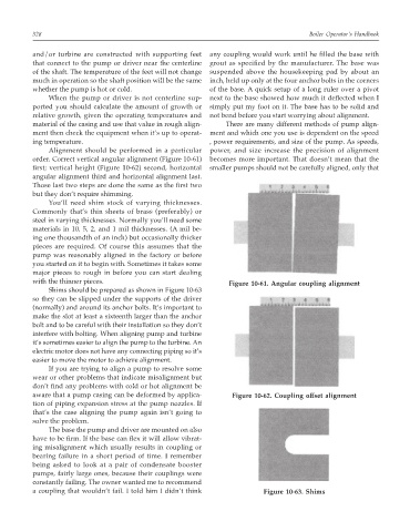
Shims should be prepared as shown in Figure 10-63
so they can be slipped under the supports of the driver
(normally) and around its anchor bolts. It’s important to
make the slot at least a sixteenth larger than the anchor
bolt and to be careful with their installation so they don’t
interfere with bolting. When aligning pump and turbine
it’s sometimes easier to align the pump to the turbine. An
electric motor does not have any connecting piping so it’s
easier to move the motor to achieve alignment.
If you are trying to align a pump to resolve some
wear or other problems that indicate misalignment but
don’t find any problems with cold or hot alignment be
aware that a pump casing can be deformed by applica- Figure 10-62. Coupling offset alignment
tion of piping expansion stress at the pump nozzles. If
that’s the case aligning the pump again isn’t going to
solve the problem.
The base the pump and driver are mounted on also
have to be firm. If the base can flex it will allow vibrat-
ing misalignment which usually results in coupling or
bearing failure in a short period of time. I remember
being asked to look at a pair of condensate booster
pumps, fairly large ones, because their couplings were
constantly failing. The owner wanted me to recommend
a coupling that wouldn’t fail. I told him I didn’t think Figure 10-63. Shims