
Page 345 - Boiler_Operators_Handbook,_Second_Edition
P. 345
330 Boiler Operator’s Handbook
ing each foot the same. If you don’t have a micrometer because that’s what we always say. You really aren’t
use the ruler and light to compare the pieces of shim aligning the coupling, you’re aligning the shafts of the
stock. Before you work on horizontal alignment check pump and driver but we still say we’re aligning the
the vertical with the driver bolted down on the shims. coupling. Anyway, better is done with a dial micrometer
Sometimes the shims can compress a little more or less (Figure 10-67) which eliminates problems with poorly
to alter the alignment. machined couplings and provides hard readings instead
Once you’ve got vertical alignment down the jobs of eyeballing it. You determine the error by clamping
simpler because you don’t have to mess with the shim mounting bars furnished with the micrometer to hold it
stock. It is, however, hard to retain angular position relative to one coupling half while the micrometer stub
horizontally while you’re trying to correct centerline (sticking out at the bottom left of the figure) rests against
alignment. I always preferred the light hammer method. the half coupling attached to the other shaft, zeroing the
Once I got the pump close I used a small hammer to tap micrometer, then rotating the shafts to take a reading
the feet. Once you get used to it you’ll discover about 180 degrees from the original one.
how hard you have to tap to get a movement of one mil. Zeroing the micrometer is accomplished by simply
Tapping both feet on one side consistently will shift the grabbing the dial and twisting it until the zero is cen-
driver the same amount to retain angular displacement. tered under the needle. In this case you use twice the
For better precision in aligning a pump and driv- distance from the center of the shaft to the contact point
er… Okay, I’ll relent, I should say aligning a coupling of the micrometer instead of the length of the coupling
to determine the ratio. Usually the ratio is close to one,
making life a little easier, just use a shim matching the
reading.
There are more precise methods using laser equip-
ment and computers but that’s best handled by a con-
tractor that specializes in alignment. You have to align a
lot of pumps in order to justify the cost of a laser align-
ment system.
NPSH
It stands for ‘net positive suction head’ and despite
it being one of those terms that we engineers use it’s ab-
solutely essential that an operator understand what it is
and how it relates to the operation of pumps. In many a
discussion we’ll use the term to mean one of two things
without clarifying it and in other cases we’ll clarify that
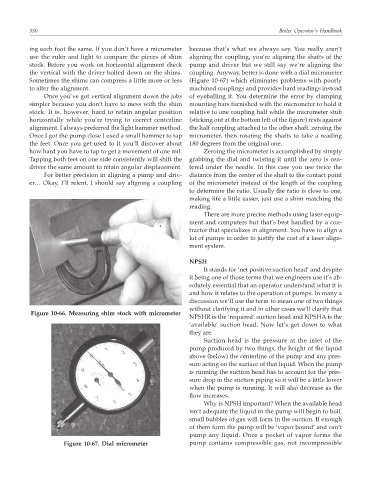
Figure 10-66. Measuring shim stock with micrometer
NPSHR is the ‘required’ suction head and NPSHA is the
‘available’ suction head. Now let’s get down to what
they are.
Suction head is the pressure at the inlet of the
pump produced by two things, the height of the liquid
above (below) the centerline of the pump and any pres-
sure acting on the surface of that liquid. When the pump
is running the suction head has to account for the pres-
sure drop in the suction piping so it will be a little lower
when the pump is running. It will also decrease as the
flow increases.
Why is NPSH important? When the available head
isn’t adequate the liquid in the pump will begin to boil,
small bubbles of gas will form in the suction. If enough
of them form the pump will be ‘vapor bound’ and can’t
pump any liquid. Once a pocket of vapor forms the
Figure 10-67. Dial micrometer pump contains compressible gas, not incompressible