
Page 344 - Boiler_Operators_Handbook,_Second_Edition
P. 344
Plants and Equipment 329
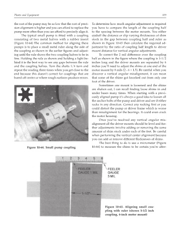
the cost of the pump may be so low that the cost of preci- To determine how much angular adjustment is required
sion alignment is higher and you can afford to replace the you have to compare the length of the coupling half
pump more often than you can afford to precisely align it. to the spacing between the motor mounts. You either
The typical small pump is fitted with a coupling eyeball the distance or slip varying thicknesses of shim
consisting of two metal halves with a rubber insert stock in the gap between coupling half and ruler as
(Figure 10-64) The common method for aligning these shown in Figure 10-65 then calculate the required ad-
pumps is to place a small metal ruler along the side of justment by the ratio of coupling half length to driver
the coupling as shown in the earlier figures and adjust- mount distance for vertical angular adjustments.
ing until the rule shows the two coupling halves to be in To correct the 2 mil difference over the coupling
line. Holding the rule as shown and holding a light be- half as shown in the figure where the coupling is 1-1/2
hind it is the best way to see any gaps between the rule inches long and the driver mounts are separated by 6
and the coupling halves. Turn the shafts 1/4 turn and inches you’ll need to adjust the shims at one end of the
repeat the reading three times when you get close to the motor mount by 8 mils (2 6 ÷ 1.5). Be careful when you
*
end because this doesn’t correct for couplings that are discover a vertical angular misalignment, it can mean
bored off center or where rough surfaces produce errors. that some of the shims got knocked out from only one
foot of the driver.
Sometimes one mount is loosened and the shims
are shaken out, I can recall finding loose shims in and
under bases many times. When starting with a previ-
ously aligned pump it’s always a good idea to loosen all
the anchor bolts of the pump and driver and see if either
rocks in any direction. Correct any rocking first or you
could distort the pump or driver frame which is worse
than misalignment for the bearings. It could even crack
the motor housing.
Once you’ve resolved any vertical angular mis-
alignment all the driver mounts should be level and fur-
ther adjustments involve adding or removing the same
amount of shim stock under each of the feet. Be careful
when performing the vertical center alignment because
you can add or remove different thicknesses of shims.
The best thing to do is use a micrometer (Figure
Figure 10-64. Small pump coupling 10-66) to measure the shims to be certain you’re alter-
Figure 10-65. Aligning small cou-
pling with ruler (shown 1-1/2 inch
coupling, 6-inch motor mount)