
Page 408 - Boiler_Operators_Handbook,_Second_Edition
P. 408
Controls 393
Two Element Control need for additional hardware; that’s why we can make
To reduce the impact of shrink and swell a water a two element controller out of a single element one by
system that doesn’t enhance the effect of it is required. simply wiring the steam flow signal to the drum level
Two and three element systems actually counter some of controller. Actually, in many systems and any future
the effect by adding water when the level is swelling up system it is simply a matter of telling the controller to
to quench bubbles which reduces the swell. Conversely get the steam flow signal because all the controllers have
they reduce the addition of colder feedwater when the access to all the signals in a system.
level is shrinking. The two and three element systems control the
I mentioned single element control operation. feedwater valve in proportion to steam flow with an
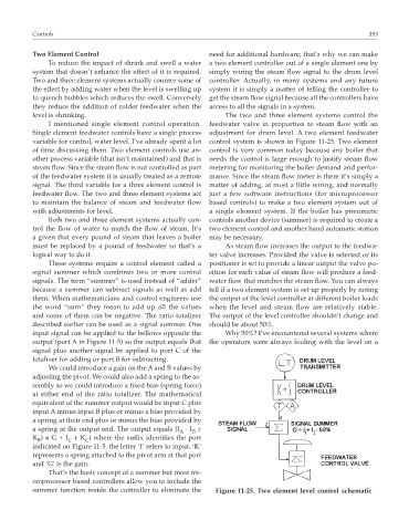
Single element feedwater controls have a single process adjustment for drum level. A two element feedwater
variable for control, water level. I’ve already spent a lot control system is shown in Figure 11-25. Two element
of time discussing them. Two element controls use an- control is very common today because any boiler that
other process variable (that isn’t maintained) and that is needs the control is large enough to justify steam flow
steam flow. Since the steam flow is not controlled as part metering for monitoring the boiler demand and perfor-
of the feedwater system it is usually treated as a remote mance. Since the steam flow meter is there it’s simply a
signal. The third variable for a three element control is matter of adding, at most a little wiring, and normally
feedwater flow. The two and three element systems act just a few software instructions (for microprocessor
to maintain the balance of steam and feedwater flow based controls) to make a two element system out of
with adjustments for level. a single element system. If the boiler has pneumatic
Both two and three element systems actually con- controls another device (summer) is required to create a
trol the flow of water to match the flow of steam. It’s two element control and another hand automatic station
a given that every pound of steam that leaves a boiler may be necessary.
must be replaced by a pound of feedwater so that’s a As steam flow increases the output to the feedwa-
logical way to do it. ter valve increases. Provided the valve is selected or its
These systems require a control element called a positioner is set to provide a linear output the valve po-
signal summer which combines two or more control sition for each value of steam flow will produce a feed-
signals. The term “summer” is used instead of “adder” water flow that matches the steam flow. You can always
because a summer can subtract signals as well as add tell if a two element system is set up properly by noting
them. When mathematicians and control engineers use the output of the level controller at different boiler loads
the word “sum” they mean to add up all the values when the level and steam flow are relatively stable.
and some of them can be negative. The ratio totalizer The output of the level controller shouldn’t change and
described earlier can be used as a signal summer. One should be about 50%.
input signal can be applied to the bellows opposite the Why 50%? I’ve encountered several systems where
output (port A in Figure 11-5) so the output equals that the operators were always fooling with the level on a
signal plus another signal be applied to port C of the
totalizer for adding or port B for subtracting.
We could introduce a gain on the A and B values by
adjusting the pivot. We could also add a spring to the as-
sembly so we could introduce a fixed bias (spring force)
at either end of the ratio totalizer. The mathematical
equivalent of the summer output would be input C plus
input A minus input B plus or minus a bias provided by
a spring at their end plus or minus the bias provided by
a spring at the output end. The output equals (I - I ±
A B
K ) × G + I ± K ) where the suffix identifies the port
B C C
indicated on Figure 11-5, the letter ‘I’ refers to input, ‘K’
represents a spring attached to the pivot arm at that port
and ‘G’ is the gain.
That’s the basic concept of a summer but most mi-
croprocessor based controllers allow you to include the
summer function inside the controller to eliminate the Figure 11-25. Two element level control schematic