
Page 181 - Bridge and Highway Structure Rehabilitation and Repair
P. 181
156 SECTION 2 STRENGTHENING AND REPAIR WORK
Max. sheer stress
3 w
3
4 bd
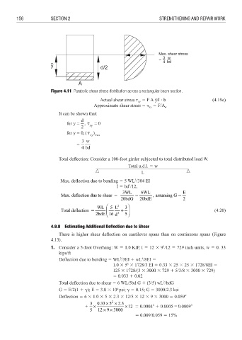
Figure 4.11 Parabolic shear stress distribution across a rectangular beam section.
Actual shear stress 3 F A y˘/I b (4.19e)
xy
Approximate shear stress 3 3 F/A
xy w
It can be shown that:
Total deflection: Consider a 100-foot girder subjected to total distributed load W.
Total u.d.l. 3 w
________________________________________
L
3
Max. deflection due to bending 3 5 WL /384 EI
I 3 bd /12;
3
3WL 6WL E
Max. deflection due to shear 3 3 , assuming G 3
20bdG 2 20bdE 2
WL 5 L 2 3
Total deflection 3 + (4.20)
2bdE 16 d 2 5
4.9.8 Estimating Additional Deflection due to Shear
There is higher shear deflection on cantilever spans than on continuous spans (Figure
4.13).
1. Consider a 5-foot Overhang: W 3 1.0 KIP, I 3 12 8 9 /12 3 729 inch units, w 3 0. 33
3
kips/ft
Deflection due to bending 3 WL /3EI 4 wL /8EI 3
3
4
3
1.0 8 5 8 1728/3 EI 4 0.33 8 25 8 25 8 1728/8EI 3
125 8 1728/(3 8 3000 8 729 4 5/3/8 8 3000 8 729)
3 0.033 4 0.02
2
Total deflection due to shear 3 6 WL/5bd G 4 (3/5) wL /bdG
6
G 3 E/2(1 4 ); E 3 3.0 8 10 psi; 3 0.15; G 3 3000/2.3 ksi
Defl ection 3 6 8 1.0 8 5 8 2.3 8 12/5 8 12 8 9 8 3000 3 0.0592
×
2
3 0.33 5 × 23 .
+ × ×12 3 0.00042 4 0.0005 = 0.00092
5 12 9
×× 3000
3 0.009/0.059 3 15%