
Page 176 - Bridge and Highway Structure Rehabilitation and Repair
P. 176
CHAPTER 4 AN ANALYTICAL APPROACH TO FRACTURE AND FAILURE 151
x
s y d x
longitudinal
m y d x
S 4 dS x
x
dW
M x 4 dM x
M x y
dx T x 4 dT x
T x
S x (s y 4
y s y )d x
(m y 4 m y )d x
transverse
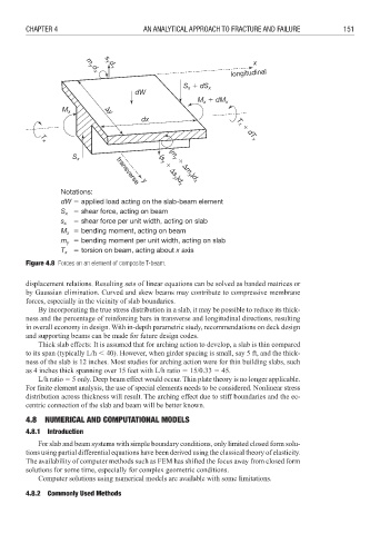
Notations:
dW 3 applied load acting on the slab-beam element
S x 3 shear force, acting on beam
s x 3 shear force per unit width, acting on slab
M 3 bending moment, acting on beam
x
m 3 bending moment per unit width, acting on slab
y
T x 3 torsion on beam, acting about x axis
Figure 4.8 Forces on an element of composite T-beam.
displacement relations. Resulting sets of linear equations can be solved as banded matrices or
by Gaussian elimination. Curved and skew beams may contribute to compressive membrane
forces, especially in the vicinity of slab boundaries.
By incorporating the true stress distribution in a slab, it may be possible to reduce its thick-
ness and the percentage of reinforcing bars in transverse and longitudinal directions, resulting
in overall economy in design. With in-depth parametric study, recommendations on deck design
and supporting beams can be made for future design codes.
Thick slab effects: It is assumed that for arching action to develop, a slab is thin compared
to its span (typically L/h : 40). However, when girder spacing is small, say 5 ft, and the thick-
ness of the slab is 12 inches. Most studies for arching action were for thin building slabs, such
as 4 inches thick spanning over 15 feet with L/h ratio 3 15/0.33 3 45.
L/h ratio 3 5 only. Deep beam effect would occur. Thin plate theory is no longer applicable.
For finite element analysis, the use of special elements needs to be considered. Nonlinear stress
distribution across thickness will result. The arching effect due to stiff boundaries and the ec-
centric connection of the slab and beam will be better known.
4.8 NUMERICAL AND COMPUTATIONAL MODELS
4.8.1 Introduction
For slab and beam systems with simple boundary conditions, only limited closed form solu-
tions using partial differential equations have been derived using the classical theory of elasticity.
The availability of computer methods such as FEM has shifted the focus away from closed form
solutions for some time, especially for complex geometric conditions.
Computer solutions using numerical models are available with some limitations.
4.8.2 Commonly Used Methods