
Page 172 - Bridge and Highway Structure Rehabilitation and Repair
P. 172
CHAPTER 4 AN ANALYTICAL APPROACH TO FRACTURE AND FAILURE 147
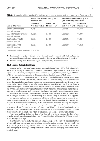
Table 4.2 Comparative solutions using the differential equations approach for two-way bending of a square panel (Poisson ratio = 0).
Relative Slab: Beam Stiffness 0 Relative Slab: Beam Stiffness
(Beamless deck) (Stiff beams/simply supported)
Central Slab Central Slab Central Slab Central Slab
4
4
Method of Solutions Defl ection qL /D Moment qL 2 Defl ection qL /D Moment qL 2
Galerkin solution for partial 0.0287 — 0.00456 0.03684
composite boundary
S. J. Fuch’s* solution for partial 0.0282 0.1055 0.004062 0.03941
composite boundary
Khan’s solution for partial 0.0285 0.1056 0.004048 0.03604
composite boundary
Khan’s solution for full 0.0285 0.1056 0.004049 0.03606
composite boundary
* Proceedings of ASCE, Vol. 79, Separate No. 199, 1953.
7. In a through two-girder system, the ends of the slab panels composite with the floor beam are
connected in the tension zone of the through girder and are subjected to overall tension.
8. Stresses arising from sharp skew edges accompanied by stress concentrations.
4.7.2 Arching Action in Deck Slabs
Arching action in slab and beam systems was studied as early as 1953 by B. G. Galerkin in
Moscow and later by Allen and Severn at Bristol University and by Khan and Kemp at the Univer-
sity of London. Recently investigations were conducted by Csagoly, Hewitt, and Klinger. AASHTO
LRFD recommends incorporating arching action in the detailed design of deck slabs.
AASHTO C9.7.2.1 states that arching action occurs in deck slabs and an internal compressive
dome is created. Near the boundaries, bending stress is accompanied by axial or planar stress.
When the magnitude of axial stress exceeds the bending stress in tension, the net stress is overall
compression. Dome effect appears to be greater at the corners of the slab panel, where the deck
rotates in a diagonal direction. Dome action would occur at the beam supports due to slab bend-
ing in the diagonal direction in opposite panels of multiple panels. The deflected shape of a deck
slab can be idealized as an arch over supporting beams and usually a reverse arch at midspan.
Both dead load and live load deflected shapes are additive and are similar reverse curves. Beam
action changes to arch action with the full depth of the slab acting in compression at supports.
At supports such as piers and abutments, additional stiffness is provided to composite sec-
tions in transverse directions by diaphragms, even though they are not directly in contact with
concrete. It minimizes one-way bending of the deck slab and introduces two-way bending local
to stiffened composite section. A transverse strip of slab over supports tends to act as a concealed
or secondary beam. To prevent cracking of concrete, additional reinforcing bars in strips in the
direction of the diaphragms would reduce any overstress. A similar effect is observed in fl at or
beamless slabs in building floors, where column strips are designed as concealed beams.
Transverse and longitudinal bending of the slab will give rise to diagonal bending of slab
strips between diagonally opposite bearings. Diagonal bending will be smaller if the aspect ratio
of the panel (L/a) is large.
Near the corners of panels, the diagonal defl ected shape of the slab will be in the form of
a dome with predominant local compression and rapid transition to tension at midspan (Figure
4.5). Detailing of reinforcing bars at present does not take into account true stress distribution.
This inadequacy in detailing is partly responsible for slab cracks, a nagging maintenance prob-
lem in bridges.