
Page 171 - Bridge and Highway Structure Rehabilitation and Repair
P. 171
146 SECTION 2 STRENGTHENING AND REPAIR WORK
,
,
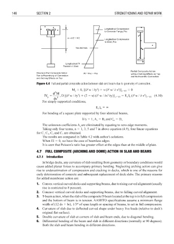
Partial Composite Action
Figure 4.4 Full and partial composite action between slab and beam due to geometry of connection.
2
M 3 0, [(; w / ;y ) 4 ' (; w/ ; x )] y3b/2 3 0
2
2
2
y
2
dM
IV 3 , D [(; w / ;y ) 4 (2 6 ') (; w / ;x ;y)] 3 E I (; w / ; x ) (4.10)
4
3
3
4
2
3
y 2 y3b/2 b b y3b/2
dx
For simply supported conditions,
E I 3
b b
For bending of a square plate supported by four identical beams,
/ 3 1, A 3 B and C 3 D n
n
n
n
The unknown coeffi cients A are eliminated by equating to zero edge moments.
n
Taking only four terms, n 3 1, 3, 5 and 7 in above equation (4.9), four linear equations
for C C , C and C are obtained.
7
1,
3
5
The results are compared in Table 4.2 with author’s solutions.
When EI 3 0, we have the case of beamless edges.
It is seen that Poisson’s ratio has greater effect at the edges than at the middle of plate.
4.7 FULL COMPOSITE (ARCHING AND DOME) ACTION IN SLAB AND BEAMS
4.7.1 Introduction
In bridge decks, any curvature of slab resulting from geometry or boundary conditions would
cause added planar forces to accompany primary bending. Neglecting arching action can give
rise to underestimation of compression and cracking in decks, which is one of the reasons for
early deterioration of concrete and subsequent replacement of deck slabs. The primary reasons
for added membrane action are:
1. Convex vertical curved decks and supporting beams, due to rising curved alignment (usually
rise is restricted to 8 percent).
2. Concave vertical curved decks and supporting beams, due to falling curved alignment.
3. T-beam action, when the slab of the composite T-beam located at the top is in full compression
and the bottom of beam is in tension. AASHTO specifications assume a minimum fl ange
width of (12 ds 4 br), 1/3 of span length or spacing of beams, to act in full compression.
rd
4. Curvature of slab due to deflected curved shape under heavy live loads (relative to deck’s
original fl at surface).
5. Double curvature of slab at corners of slab and beam ends, due to diagonal bending.
6. Differential bending of the beam and slab in different directions (normally at 90 degrees).
Both the slab and beam bending in different directions.