
Page 175 - Bridge and Highway Structure Rehabilitation and Repair
P. 175
150 SECTION 2 STRENGTHENING AND REPAIR WORK
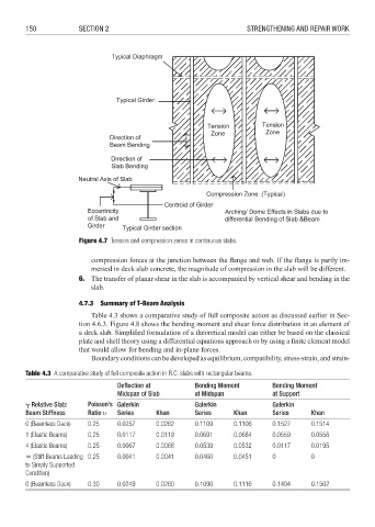
Figure 4.7 Tension and compression zones in continuous slabs.
compression forces at the junction between the flange and web. If the flange is partly im-
mersed in deck slab concrete, the magnitude of compression in the slab will be different.
6. The transfer of planar shear in the slab is accompanied by vertical shear and bending in the
slab.
4.7.3 Summary of T-Beam Analysis
Table 4.3 shows a comparative study of full composite action as discussed earlier in Sec-
tion 4.6.3. Figure 4.8 shows the bending moment and shear force distribution in an element of
a deck slab. Simplifi ed formulation of a theoretical model can either be based on the classical
plate and shell theory using a differential equations approach or by using a finite element model
that would allow for bending and in-plane forces.
Boundary conditions can be developed as equilibrium, compatibility, stress-strain, and strain-
Table 4.3 A comparative study of full composite action in R.C. slabs with rectangular beams.
Defl ection at Bending Moment Bending Moment
Midspan of Slab at Midspan at Support
Relative Slab: Poisson’s Galerkin Galerkin Galerkin
Beam Stiffness Ratio ' Series Khan Series Khan Series Khan
0 (Beamless Deck) 0.25 0.0257 0.0262 0.1109 0.1106 0.1527 0.1514
1 (Elastic Beams) 0.25 0.0117 0.0119 0.0691 0.0684 0.0559 0.0558
4 (Elastic Beams) 0.25 0.0067 0.0068 0.0539 0.0532 0.0117 0.0195
(Stiff Beams Leading 0.25 0.0041 0.0041 0.0460 0.0451 0 0
to Simply Supported
Condition)
0 (Beamless Deck) 0.30 0.0249 0.0260 0.1090 0.1116 0.1404 0.1502