
Page 180 - Bridge and Highway Structure Rehabilitation and Repair
P. 180
CHAPTER 4 AN ANALYTICAL APPROACH TO FRACTURE AND FAILURE 155
Figure 4.9 Linear stress distribution for shallow beams.
If R1 r1 is initial radius of neutral axis, and R2 is fi nal radius,
Net strain ‘e’ under load is e 3 (1/R2 6 1/R1) y (4.18a)
Bending equation may be expressed as
%/y 3 E (1/R2 6 1/R1) 3 M/I (4.18b)
A correction factor in strain and stress values needs to be applied.
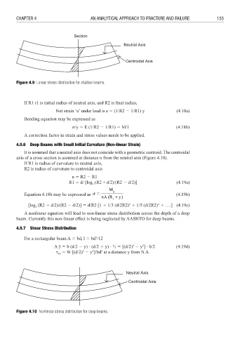
4.9.6 Deep Beams with Small Initial Curvature (Non-linear Strain)
It is assumed that a neutral axis does not coincide with a geometric centroid. The centroidal
axis of a cross section is assumed at distance n from the neutral axis (Figure 4.10).
If R1 is radius of curvature to neutral axis,
R2 is radius of curvature to centroidal axis
n 3 R2 6 R1
R1 3 d/ [log (R2 + d/2)/(R2 6 d/2)] (4.19a)
e
M y
Equation 4.18b may be expressed as %3 nA (R + (4.19b)
1 y)
2
4
[log (R2 4 d/2)/(R2 6 d/2)] 3 d/R2 [1 4 1/3 (d/2R2) 4 1/5 (d/2R2) 4 ….] (4.19c)
e
A nonlinear equation will lead to non-linear stress distribution across the depth of a deep
beam. Currently this non-linear effect is being neglected by AASHTO for deep beams.
4.9.7 Shear Stress Distribution
3
For a rectangular beam A 3 bd, I 3 bd /12
2
2
A y˘ 3 b (d/2 6 y) (d/2 4 y) ½ 3 [(d/2) 6 y ] b/2 (4.19d)
2
2
3
3 W [(d/2) 6 y ]/bd at a distance y from N.A.
xy
Figure 4.10 Nonlinear stress distribution for deep beams.