
Page 170 - Bridge and Highway Structure Rehabilitation and Repair
P. 170
CHAPTER 4 AN ANALYTICAL APPROACH TO FRACTURE AND FAILURE 145
elevation is generally restricted to 8 percent. In analysis, arch geometry effects are generally
neglected compared to primary beam action.
4.6.3 Composite Action between the Deck Slab and Beams Using Classical Theory and
Numerical Methods
The widely used approaches are:
1. Composite action resulting from deflecting beams—bridge decks are subjected to an ad-
ditional deflection at the boundaries due to bending of girders.
2. Composite action resulting from geometry—eccentric connection of slab and beam.
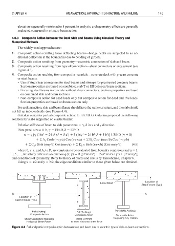
3. Composite action resulting from type of connection—shear connectors or encasement (see
Figure 4.3).
4. Composite action resulting from composite materials—concrete deck with precast concrete
or steel beams:
• Use of stud shear connectors for steel beams and stirrups for prestressed concrete beams.
Section properties are based on combined slab T or Ell between beam sections.
• Encasing steel beams in concrete without shear connectors. Section properties are based
on combined slab and beam sections.
• Non-composite action for dead loads only but composite action for dead and live loads.
Section properties are based on beam section only.
For arching action, slab and beam flange should have the same curvature, and the slab should
not lift up independently (see Figure 4.4).
Galerkin series for partial composite action: In 1953 B. G. Galerkin proposed the following
solution for slabs supported on elastic beams:
Relative stiffness of beam to slab parameters 3 , in x and y direction.
Plate panel size a 8 b, 3 EI/aD, 3 EI/bD
2
2
4
4
2
2
4
4
w 3 q [ (16x 6 24 a x 4 5 a ) 4 (16y 6 24 b y 4 5 b )] 1/384D ( 4 )
4 5 A Cosh (n!y/a) Cos (n!x/a) 4 5 B Cosh (n!x/b) Cos (n!y/b)
n
n
4 5C y Sinh (n!y/a) Cos (n!x/a) 4 5 D x Sinh (n!x/b) (Cos n!/y/b) (4.9)
n
n
where , , x, and A to D are constants to be evaluated from boundry conditions and n 3 1,
n
n
4
3, 5, …, we satisfy differential equation q (x, y) 3 D [(; w/; x ) 4 2 (; w/; x ; y ) 4 (; w/; y )]
4
4
4
2
4
2
and conditions of symmetry. Refer to theory of plates and shells by Timoshenko, Chapter 6.
Using x 3 a/2 and y 3 b/2, the edge conditions similar to those given below are obtained.
Location of
Local Bond
Slab Forces (Typ.)
N A
Location of
Beam Forces (Typ.)
Figure 4.3 Full and partial composite action between slab and beam due to eccentric type of slab-to-beam connections.