
Page 289 - Bridge and Highway Structure Rehabilitation and Repair
P. 289
264 SECTION 2 STRENGTHENING AND REPAIR WORK
The factored resistance, Rr, for gusset plates in tension shall be taken as the least of the
values given by either:
1. Yielding,
2. Fracture, or
3. The block shear rupture resistance.
• Gross Section Yielding Resistance
• Block Shear Rupture Resistance
The resistance of block shear rupture is that of combination of parallel and perpendicular
planes, one in axial tension and the remainder under shear. The factored resistance of the plate
for block shear rupture shall be considered.
Gusset Plates In Shear
The factored shear resistance, Rr, for gusset plates in shear shall be taken as the least resis-
tance against shear yielding and net section fracture.
Gusset Plates under Combined Flexural and Axial Loads
1. The maximum elastic stress from combined factored flexural and axial loads
:)fFy based on the gross area of the plate.
where:
)f 3 resistance factor for fl exure 3 1.00
Fy 3 specified minimum yield strength of the plate
The analysis of gusset plates for combined flexural and axial loads involves the evaluation
of several sections to arrive at the critical section.
The large number of equations listed are based on FHWA’s latest research on the subject
and need to be developed in a computer program.
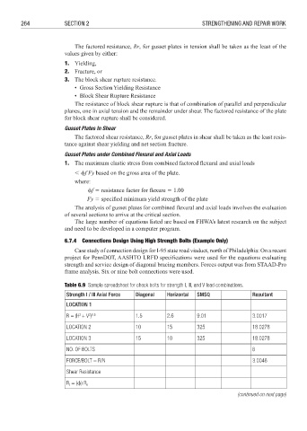
6.7.4 Connections Design Using High Strength Bolts (Example Only)
Case study of connection design for I-95 state road viaduct, north of Philadelphia: On a recent
project for PennDOT, AASHTO LRFD specifications were used for the equations evaluating
strength and service design of diagonal bracing members. Forces output was from STAAD-Pro
frame analysis. Six or nine bolt connections were used.
Table 6.9 Sample spreadsheet for check bolts for strength I, III, and V load combinations.
Strength I / III Axial Force Diagonal Horizontal SMSQ Resultant
LOCATION 1
2
R = (H + V ) 1.5 2.6 9.01 3.0017
2 0.5
LOCATION 2 10 15 325 18.0278
LOCATION 3 15 10 325 18.0278
NO. OF BOLTS 6
FORCE/BOLT = R/N 3.0046
Shear Resistance
= ()) R
R t n
(continued on next page)