
Page 294 - Bridge and Highway Structure Rehabilitation and Repair
P. 294
CHAPTER 6 APPLICATIONS OF BRIDGE DESIGN AND RATING METHODS 269
Maximum DL negative moment at supports 36wl /10 360.30 8 30 /10 3
2
2
627.0 kip-ft
Per ft width 3 27.0/5.8 ft 3 4 4.66 kip-ft/ft
2
Maximum positive moment at 0.4 L= 4 wl /12 3 4 0.30 8 30 /12 3 22.5 kip-ft
2
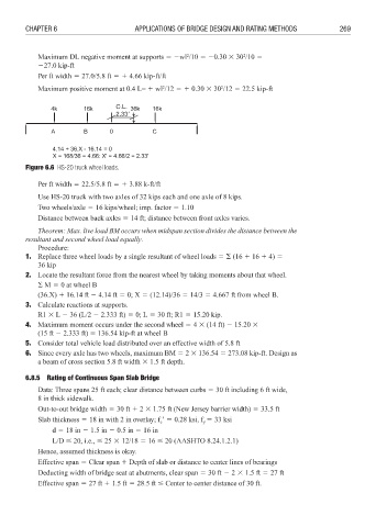
C.L.
2.331
Figure 6.6 HS-20 truck wheel loads.
Per ft width 3 22.5/5.8 ft 3 4 3.88 k-ft/ft
Use HS-20 truck with two axles of 32 kips each and one axle of 8 kips.
Two wheels/axle 3 16 kips/wheel; imp. factor 3 1.10
Distance between back axles 3 14 ft; distance between front axles varies.
Theorem: Max. live load BM occurs when midspan section divides the distance between the
resultant and second wheel load equally.
Procedure:
1. Replace three wheel loads by a single resultant of wheel loads 3 $ (16 4 16 4 4) 3
36 kip
2. Locate the resultant force from the nearest wheel by taking moments about that wheel.
$ M 3 0 at wheel B
(36.X) 4 16.14 ft 6 4.14 ft 3 0; X 3 (12.14)/36 3 14/3 3 4.667 ft from wheel B.
3. Calculate reactions at supports.
R1 8 L 6 36 (L/2 6 2.333 ft) 3 0; L 3 30 ft; R1 3 15.20 kip.
4. Maximum moment occurs under the second wheel 3 4 8 (14 ft) 6 15.20 8
(15 ft 6 2.333 ft) 3 136.54 kip-ft at wheel B
5. Consider total vehicle load distributed over an effective width of 5.8 ft
6. Since every axle has two wheels, maximum BM 3 2 8 136.54 3 273.08 kip-ft. Design as
a beam of cross section 5.8 ft width 8 1.5 ft depth.
6.8.5 Rating of Continuous Span Slab Bridge
Data: Three spans 25 ft each; clear distance between curbs 3 30 ft including 6 ft wide,
8 in thick sidewalk.
Out-to-out bridge width 3 30 ft 4 2 8 1.75 ft (New Jersey barrier width) 3 33.5 ft
Slab thickness 3 18 in with 2 in overlay; f 1 3 0.28 ksi, f 3 33 ksi
y
c
d 3 18 in 6 1.5 in 6 0.5 in 3 16 in
L/D 20, i.e., 25 8 12/18 3 16 20 (AASHTO 8.24.1.2.1)
Hence, assumed thickness is okay.
Effective span 3 Clear span 4 Depth of slab or distance to center lines of bearings
Deducting width of bridge seat at abutments, clear span 3 30 ft 6 2 8 1.5 ft 3 27 ft
Effective span 3 27 ft 4 1.5 ft 3 28.5 ft Center to center distance of 30 ft.