
Page 298 - Bridge and Highway Structure Rehabilitation and Repair
P. 298
CHAPTER 6 APPLICATIONS OF BRIDGE DESIGN AND RATING METHODS 273
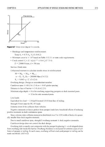
Figure 6.7 Stress-strain diagram for concrete.
• Shrinkage and temperature reinforcement:
Temp A 0.75 A / f (5.10.8.2)
s
g
y
• Minimum cover is 1.02 based on Table 5.12.3.1 or state code requirements.
• Crack control: f Z / (d A) 0.33 0.6 f (5.7.3.4)
s
y
c
Z 3 23000 N/mm, d 50 mm
Service I limit state.
Unfactored moment to calculate tensile stress in reinforcement
M 3 M DC 4 M DW 4 M LL4I
n 3 E / E , Es 3 200000 Mpa (5.4.3.2)
s
c
E 3 0.043 f 1 (5.4.2.4)
c
c
c
Overhang design: Design as nonredundant member.
Cantilever span 6 ft (3.6.1.3.4) or 0.65 girder spacing.
Distance to face of barrier 3 ft (4.6.2.2.1)
Minimum edge depth 3 8 in for overhang supporting parapets or deck mounted posts
3 12 in for side mounted posts.
Live loads:
Equivalent live load 3 1.0 kip/ft located 1.0 ft from face of railing.
Strength I limit state for HL-93 loads
Extreme event II for collision from vehicles
Negative moments at fascia girders from parapet loads have beneficial effects of reducing
positive moments in deck continuous spans.
Since extreme state collision moment is distributed over 5 to 10 ft width of deck, it is gener-
ally smaller than deck negative moment.
Due to small cantilever span, strength I overhang moment deck negative moments.
Cantilever design does not control the deck design.
Overhang slab is usually cast composite with the parapet by placing U- or ell-shaped rebars
from overhang slab inside the barrier. Overhang thickness is increased for extreme cases of col-
lision of parapet or railing. In such cases, overhang will not crack,and parapet or railing can be
made sacrifi cial. (A13.4.2)