Page 302 - Bridge and Highway Structure Rehabilitation and Repair
P. 302

CHAPTER 6                       APPLICATIONS OF BRIDGE DESIGN AND RATING METHODS            277


            Total prestress losses 3 (  f pES  4  f pTL  6  f ) (LRFD 5.9.5.1)
                                                   pRI
            Loss due to elastic shortening   f  3 E f  /E  (LRFD 5.9.5.2.3a)
                                        pES
                                              p cg p
                                                     ci
                               2
               f  3 (P /A 4 P  e  / I 6 M e / I)
                                      D
               cg p
                             i
                      i
            For low relaxation prestressing strands, initial prestress 3 0.75 f  (LRFD Table 5-7)
                                                                  pu
               P  3 f A  / (f A 4 fyAs) (LRFD Table 5-12)
                     py
                            py
                        ps
                PR
                               ps
            Time-dependent losses for I-girder:
               f pTL  3 33[1.0 6 0.15 (fc16 6.0)/6.0] 4 6.0 P 6 6.0 (LRFD 5.9.5.3)
                                                     PR
            Relaxation at transfer   f  3 log (24.0 t) [(f /f ) 6 0.55] f  / 40.0
                                                  pj
                                 pRI
                                                    py
                                                               pj
            For As 3 0, P  3 1 LRFD Eq. (5-8)
                        PR
                f  3 P /A 4 P  e/S b
                      pe
                              pe
                 pb
            Maximum reinforcement: (LRFD 6.5.6)
            c/d   0.42 (LRFD 5.7.3.3.1)
               e
        9. Critical shear check (LRFD 5.11.4)
            Shear check is not required if there is no visible sign of shear distress.
            Critical location for shear occurs near the supports and it is greater of d or 0.5 d (Cot 0).
                                                                                v
                                                                         v
            (LRFD 5.8.3.2)
            Effective shear depth d  is maximum of:
                               v
            0.9 d ; 0.72 h; distance between resultants of tensile and compressive forces.
                e
            Assume 0 3 30 degrees; 0.5 d  (Cot 0) 3 0.87 d   d v
                                      v
                                                     v
            Minimum transfer length 3 60 8 strand diameters (LRFD 5.11.4)
            If section is outside transfer length, full value of f  is used in calculating shear resistance.
                                                      po
            Maximum shear at critical section near supports:
            Total shear 3 V Lane  4 V Truck  8 IMP
            Nominal shear resistance 3 V 3 V 4 V 4 V  LRFD Eq (5-66)
                                      n
                                                    p
                                          s
                                               c
            For straight tendons, V 3 0
                                p
            Provide minimum transverse reinforcement:

        10. Modified Compression Field Theory (MCFT)
            V Lane  3 0.0316 (fc1)  b S / f  (LRFD 5.8.2.5)
                             0.5
                                     y
                                v
                               0.5
            V Lane  3 0.0316   (fc1)  b  d  LRFD Eq (5-68)
                                     v
                                   v
              V  3 A  f d Cot 0 / S LRFD Eq (5-69)
                s
                        v
                     v y
        11. Simplified approach for shear design

            0 3 45 degrees;   3 2
                             0.5
            V 3 0.0316   (fc1)  b d v
              c
                                v
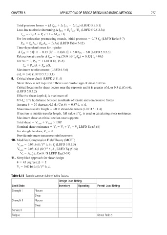
        Table 6.11  Sample summary table of rating factors.
                                        Design Load Rating
         Limit State                    Inventory   Operating    Permit Load Rating
         Strength I     Flexure
                        Shear
         Strength II    Flexure
                        Shear
         Service II
         Fatigue                                                 Stress Ratio 5
   297   298   299   300   301   302   303   304   305   306   307