
Page 119 - Build Your Own Quadcopter_ Power Up Your Designs with the Parallax Elev-8
P. 119
98 Bu il d Y o ur O w n Q u a d c o p t e r
Figure 5.5 BLDC stator wiring diagram.
Also critical to motor rotation is the electrical supply that powers the stator. It is
effectively a three-phase power supply that is created by an ESC, which in turn is connected
to the stator. A simplified wiring diagram is shown in Figure 5.5.
This figure reflects a portion of the wiring that illustrates how the three leads from the
ESC are connected to the stator coils. The A-, B-, and C-connection points alternately conduct
current in such a way that the stator creates a rotating magnetic field. If you trace the wire
from the A terminal, you can see that it wraps around stator pole 1 in a clockwise direction,
and also, through stator pole 11 in a counterclockwise direction. The net effect of opposite
current flow is to create opposite magnetic poles at each of the physical stator poles. These
electromagnetic poles are close to the PM poles on the rotor assembly. This whole interaction
causes the rotor to move while the electromagnetic poles are moved through the current
switching that is happening through the A, B, and C terminals. I realize this is all a bit
confusing, but the whole action is carefully orchestrated by the programming contained in
the ESC, which is designed to work with the fixed physical dimensions of the stator and
rotor poles. The beauty of this scheme is that the ESC need control only the rate at which it
sends current pulses to the motor, which then directly control the motor’s rotational speed.
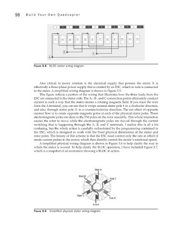
A simplified physical wiring diagram is shown in Figure 5.6 to help clarify the way in
which the stator is wound. To help clarify the BLDC operation, I have included Figure 5.7,
which is a snapshot of an animation showing a BLDC in action.
Figure 5.6 Simplified physical stator wiring diagram.