
Page 122 - Build Your Own Quadcopter_ Power Up Your Designs with the Parallax Elev-8
P. 122
Chapter 5: Quadcopter Propulsors 101
Feature Description
Flash memory 8 kB capable of in-system programming
RAM 512 B
SRAM 2 kB (holds configuration data)
Max clock speed 8 MHz (internal R/C oscillator)
Analog-to-digital conversion 8 channels with 10 bit accuracy
Operating voltage/current 2.7 to 5.5 V/1 mA (idle) to 3.6 mA (active)
Interrupts 2 external
Counters/timers Two 8-bit Timer/Counter, One 16-bit Timer/Counter
PWM 3 PWM channels
Serial interfaces 1 USART, 1 SPI, 1 I C
2
Real-time counter 1 System counter with separate oscillator
Table 5.1 Key ATmega8L Specifications
and C power leads. You can think of the MOSFETs as a series of high-speed, solid-state power
switches. They are connected in parallel to be able to handle the high currents associated with
quadcopter operations. I have included a detailed ESC schematic on this book's website,
www.mhprofessional.com/quadcopter, for those readers who are interested in looking at an
actual circuit for a typical ESC. This schematic shows the circuitry for a Tower Pro series ESC
rated for a peak 25-A load.
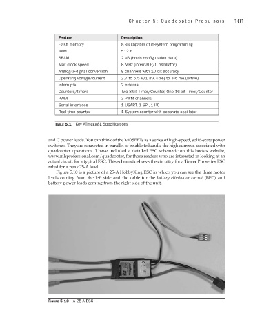
Figure 5.10 is a picture of a 25-A HobbyKing ESC in which you can see the three motor
leads coming from the left side and the cable for the battery eliminator circuit (BEC) and
battery power leads coming from the right side of the unit.
Figure 5.10 A 25-A ESC.