
Page 125 - Build Your Own Quadcopter_ Power Up Your Designs with the Parallax Elev-8
P. 125
104 Bu il d Y o ur O w n Q u a d c o p t e r
Notice that the current rating is 15 A. This means it is very conservatively rated for this
application, in which the maximum current should not be more than 5 A. The maximum
voltage is also conservative, since the real battery voltage will likely remain below 13 V. The
key take away from this specification review is that the 30-A Elev-8 ESCs should easily
handle any normal flight operations without being overstressed or overheated.
Next, I will discuss the waveforms associated with ESC operations, which will help you
understand how the ESC functions. I am postponing the BEC discussion until later in this
chapter in order to establish a good foundation to understand what happens with the BEC
circuits.
ESC Waveforms
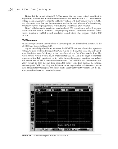
An oscilloscope captures the waveform of typical signals that are sent from the MCU to the
MOSFETs, as shown in Figure 5.13.
A gate control signal will turn on one of the MOSFET columns when it has a positive
voltage. You can see from the figure that Gate A is on for 1 ms, then turns off, and Gate B
immediately turns on. Gate B stays on for 1 ms, shuts off, and Gate C turns on for 1 ms. The
whole process repeats every 3 ms, or approximately 333 Hz. This is the origin of the three-
phase operation that I mentioned earlier in the chapter. Remember, a positive gate voltage
will turn on the MOSFETs to which it is connected. The MOSFETs will then conduct and
allow current to flow through their connected motor coils, thus causing the rotating
electromagnetic field. It is a fairly simple but somewhat elegant scheme that creates a pseudo
three-phase motor whose speed and torque can be closely controlled by the MCU in the ESC
in response to external servo-control signals.
Figure 5.13 Gate control signals from MCU to MOSFETs.