
Page 128 - Build Your Own Quadcopter_ Power Up Your Designs with the Parallax Elev-8
P. 128
Chapter 5: Quadcopter Propulsors 107
Figure 5.17 Experimental test-circuit diagram.
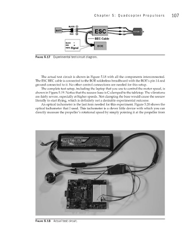
The actual test circuit is shown in Figure 5.18 with all the components interconnected.
The ESC BEC cable is connected to the BOE solderless breadboard with the BOE’s pin 14 and
ground connected to it. No other control connections are needed for this setup.
The complete test setup, including the laptop that you use to control the motor speed, is
shown in Figure 5.19. Notice that the seesaw base is C-clamped to the tabletop. The vibrations
are fairly severe, especially at higher speeds. Not clamping the base would cause the seesaw
literally to start flying, which is definitely not a desirable experimental outcome.
An optical tachometer is the last item needed for this experiment. Figure 5.20 shows the
optical tachometer that I used. This tachometer is a clever little device with which you can
directly measure the propeller’s rotational speed by simply pointing it at the propeller from
Figure 5.18 Actual test circuit.