
Page 126 - Build Your Own Quadcopter_ Power Up Your Designs with the Parallax Elev-8
P. 126
Chapter 5: Quadcopter Propulsors 105
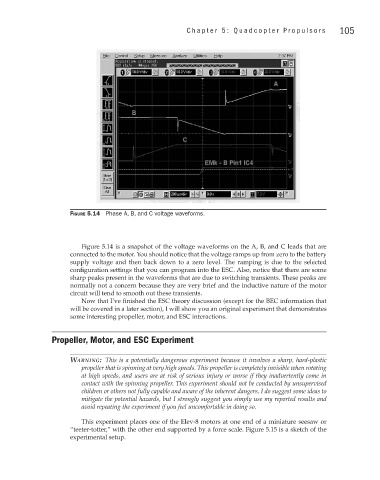
Figure 5.14 Phase A, B, and C voltage waveforms.
Figure 5.14 is a snapshot of the voltage waveforms on the A, B, and C leads that are
connected to the motor. You should notice that the voltage ramps up from zero to the battery
supply voltage and then back down to a zero level. The ramping is due to the selected
configuration settings that you can program into the ESC. Also, notice that there are some
sharp peaks present in the waveforms that are due to switching transients. These peaks are
normally not a concern because they are very brief and the inductive nature of the motor
circuit will tend to smooth out these transients.
Now that I’ve finished the ESC theory discussion (except for the BEC information that
will be covered in a later section), I will show you an original experiment that demonstrates
some interesting propeller, motor, and ESC interactions.
Propeller, Motor, and ESC Experiment
Warning: This is a potentially dangerous experiment because it involves a sharp, hard-plastic
propeller that is spinning at very high speeds. This propeller is completely invisible when rotating
at high speeds, and users are at risk of serious injury or worse if they inadvertently come in
contact with the spinning propeller. This experiment should not be conducted by unsupervised
children or others not fully capable and aware of the inherent dangers. I do suggest some ideas to
mitigate the potential hazards, but I strongly suggest you simply use my reported results and
avoid repeating the experiment if you feel uncomfortable in doing so.
This experiment places one of the Elev-8 motors at one end of a miniature seesaw or
“teeter-totter,” with the other end supported by a force scale. Figure 5.15 is a sketch of the
experimental setup.