
Page 121 - Build Your Own Quadcopter_ Power Up Your Designs with the Parallax Elev-8
P. 121
100 Bu il d Y o ur O w n Q u a d c o p t e r
Electronic Speed Controller
The primary purpose of an electronic speed controller (ESC) is to supply power to a motor that
is proportional to its control input, which is normally a servo-type signal. The ESC supplies
power to the motor via a three-phase power supply that was first discussed in the above
motor section. The power supply is strictly DC, even though I used the descriptor "three-
phase," which is normally associated with alternating current (AC) motors. The power-supply
voltage varies only between zero and the peak battery voltage and never goes negative as it
would with an AC power supply. The phasing is really about the current-pulse sequence
that is delivered to the motor and causes it to rotate. (Some figures that are shown later in
this section should help clarify the phase concept.)
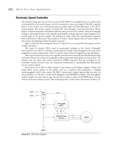
Refer to the ESC block diagram shown in Figure 5.9 as you read the description of how
an ESC functions.
The heart of modern ESCs used in quadcopter projects is the Atmel ATmega8L
microcontroller unit (MCU), which is a flash-memory-based, 8-bit microprocessor with some
peripheral-control components. Table 5.1 shows some of the ATmega8L key specifications.
These specifications reveal a very capable controller that can easily handle the demanding
real-time task of converting servo signals to their equivalent three-phase power pulses. You
should note the three pulse-width modulation (PWM) channels that are included in the
controller circuits because they are important components in generating the three-phase
power control signals.
The essence of an ESC is rather simple: it just chops up the battery supply voltage and
sends these power pulses to the motor coils in a sequence that generates a rotating
electromagnetic field in the stator. The MCU creates gate control signals that are sent via
traces labeled as A, B, and C in the block diagram to the MOSFET switches. The three-phase
control signals are next sent to gate circuits that control a series of MOSFETs that, in turn,
switch on the raw battery power. The switched power is then fed to the motor via the A, B,
Figure 5.9 ESC block diagram.