
Page 144 - Build Your Own Quadcopter_ Power Up Your Designs with the Parallax Elev-8
P. 144
Chapter 5: Quadcopter Propulsors 123
“@SingleServo” is the way Spin knows to go to a specific memory location in a cog’s
RAM to load and execute instructions. By default, the cog memory location is normally set
at 0, which is explained below in the assembly language discussion.
An infinite loop then runs and checks for a new character appearing in the fdx buffer. It
will subsequently store the clock-cycle count equivalent to the pulse width desired in the
“position” variable. Remember from the above experiment that 1 ms is 0 or no rotation,
while 2 ms is 100% or maximum rotation. 1 ms is equal to 80,000 clock cycles, while 2 ms is
equal to 160,000 clock cycles, all with respect to an 80-MHz system clock. The specific cycle
number is stored in a designated memory location in the hub RAM memory named
“position,” as previously discussed. Thus, the commanded pulse width is always available
to the newly created cog using the PAR SPR. Also, recall that the cogs are constantly being
refreshed by the hub; thus, any new values appearing in a shared hub memory location will
almost instantly appear in the appropriate cog SPR.
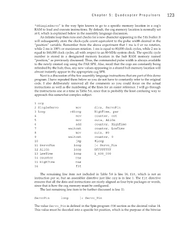
Next is a discussion of the few assembly language instructions that are part of this demo
program. I have repeated them below so you do not have to constantly refer to the original
code. I also deliberately removed all the comments so you could focus on the actual
instructions as well as the numbering of the lines for an easier reference. I will go through
the instructions one at a time in Table 5.6, since that is probably the least confusing way to
approach this somewhat complex subject.
1 org
2 SingleServo mov dira, ServoPin
3 Loop rdlong HighTime, par
4 mov counter, cnt
5 mov outa, AllOn
6 add counter, HighTime
7 waitcnt counter, LowTime
8 mov outa, #0
9 waitcnt counter, 0
10 jmp #Loop
11 ServoPin long |< Servo_Pin
12 AllOn long $FFFFFFFF
13 LowTime long 1_600_000
14 counter res
15 HighTime res
16 fit
The remaining line item not included in Table 5.6 is line 16, fit, which is not an
instruction per se, but an assembler directive just like org is in line 1. The fit directive
ensures that all the data and instructions are nicely aligned as four byte packages or words,
since that is how the cog memory must be configured.
The last remaining line item to be further discussed is line 11:
ServoPin long |< Servo_Pin
The value Servo_Pin is defined in the Spin program CON section as the decimal value 14.
This value must be decoded into a specific bit position, which is the purpose of the bitwise