
Page 145 - Build Your Own Quadcopter_ Power Up Your Designs with the Parallax Elev-8
P. 145
124 Bu il d Y o ur O w n Q u a d c o p t e r
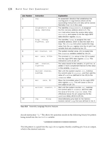
Line Number Instruction Explanation
1 org An assembler directive that establishes the
starting point in cog memory where all the
succeeding instructions and data will be stored.
Normally 0 as it is in this case
2 SingleServo mov The identifier, SingleServo, is assigned
dira, ServoPin the first memory address which is 0. The
mov instruction takes the source data value,
ServoPin, and copies it into the cog’s GPIO
data direction register, dira.
3 Loop rdlong The identifier, Loop, is assigned the next
HighTime, par available address, which is also the start of a
loop. The rdlong instruction copies the long
value from the par register into the HighTime
variable that was created by line 15.
4 mov counter, cnt The system counter value, cnt, is copied into
the counter variable created by line 14.
5 mov outa, AllOn The constant AllOn setup in line 12 is copied
into the cog’s GPIO data register, outa. This
instruction turns on pin 14.
6 add counter, The value stored in the variable, HighTime, is
HighTime added in two’s complement fashion to the value
in the variable, counter.
7 waitcnt counter, Wait until the system counter, cnt, matches
LowTime the current value in counter, and then add the
value of LowTime (defined in line 13) to the
counter value
8 mov outa, #0 Move the immediate value 0 to the cog’s GPIO
data register, outa. This will cause a zero or
low output on pin 14.
9 waitcnt counter, 0 Wait until the system counter, cnt, matches
the current value in counter and then add
the value of 0 to the counter value. This
effectively keeps the pin output low for the
LowTime value, which is 20 ms.
10 jmp #Loop Unconditionally jump back to the memory
location named Loop that was defined in line 3.
Table 5.6 Assembly Language Routine Analysis
decode instruction “|<.” The above bit operation results in the following binary bit pattern
being stored into the ServoPin variable:
%00000000 00000000 01000000 00000000
This bit pattern is copied into the cog’s dira register, thereby enabling pin 14 as an output,
which is the desired outcome.