
Page 177 - Build Your Own Quadcopter_ Power Up Your Designs with the Parallax Elev-8
P. 177
156 Bu il d Y o ur O w n Q u a d c o p t e r
Shown alongside the TM1000 module is a plastic bind stick that allows you to press a
very tiny button that is visible on the left side of the module. It takes a bit of dexterity during
the bind process to power on the receiver-telemetry module and to simultaneously press the
bind button during the binding process.
Three ports are visible on the bottom of the module:
1. RPM
2. TEMP/VOLT
3. DATA
The DATA port is committed to link the TM1000 module to the AR8000 receiver where it
plugs into the BIND/DAT port. The RPM sensor plugs into the RPM port, and a supplied
Y-Connector cable plugs into the TEMP/VOLT port. You will receive a temperature sensor
and a voltage sensor as part of the TM1000 package. The RPM sensor is a separately
purchased item, and depends on what motor type you are using. Fuel-driven engines use a
different sensor from the one used for a BLDC motor. Therefore, I purchased a BLDC sensor.
Both the voltage and temperature sensors plug into the Y-connector mentioned above.
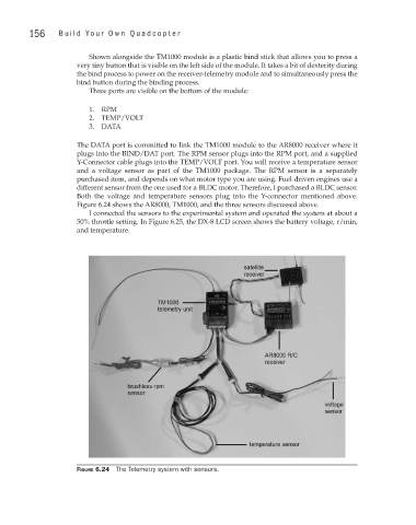
Figure 6.24 shows the AR8000, TM1000, and the three sensors discussed above.
I connected the sensors to the experimental system and operated the system at about a
50% throttle setting. In Figure 6.25, the DX-8 LCD screen shows the battery voltage, r/min,
and temperature.
Figure 6.24 The Telemetry system with sensors.