
Page 178 - Build Your Own Quadcopter_ Power Up Your Designs with the Parallax Elev-8
P. 178
Chapter 6: Radio-Controlled Systems and Telemetr y 157
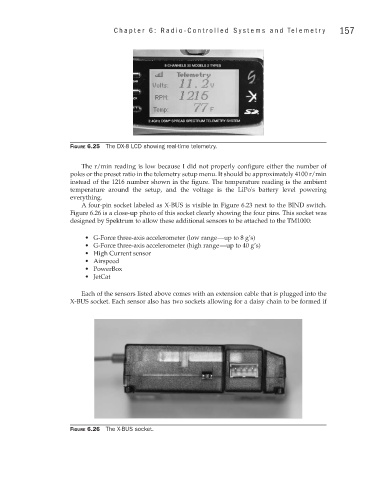
Figure 6.25 The DX-8 LCD showing real-time telemetry.
The r/min reading is low because I did not properly configure either the number of
poles or the preset ratio in the telemetry setup menu. It should be approximately 4100 r/min
instead of the 1216 number shown in the figure. The temperature reading is the ambient
temperature around the setup, and the voltage is the LiPo's battery level powering
everything.
A four-pin socket labeled as X-BUS is visible in Figure 6.23 next to the BIND switch.
Figure 6.26 is a close-up photo of this socket clearly showing the four pins. This socket was
designed by Spektrum to allow these additional sensors to be attached to the TM1000:
• G-Force three-axis accelerometer (low range—up to 8 g’s)
• G-Force three-axis accelerometer (high range—up to 40 g’s)
• High Current sensor
• Airspeed
• PowerBox
• JetCat
Each of the sensors listed above comes with an extension cable that is plugged into the
X-BUS socket. Each sensor also has two sockets allowing for a daisy chain to be formed if
Figure 6.26 The X-BUS socket.