
Page 183 - Build Your Own Quadcopter_ Power Up Your Designs with the Parallax Elev-8
P. 183
162 Bu il d Y o ur O w n Q u a d c o p t e r
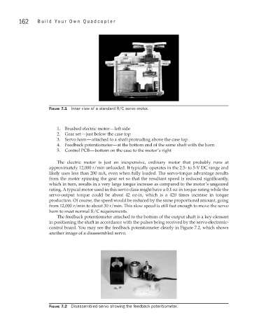
Figure 7.1 Inner view of a standard R/C servo motor.
1. Brushed electric motor—left side
2. Gear set—just below the case top
3. Servo horn—attached to a shaft protruding above the case top
4. Feedback potentiometer—at the bottom end of the same shaft with the horn
5. Control PCB—bottom on the case to the motor’s right
The electric motor is just an inexpensive, ordinary motor that probably runs at
approximately 12,000 r/min unloaded. It typically operates in the 2.5- to 5-V DC range and
likely uses less than 200 mA, even when fully loaded. The servo-torque advantage results
from the motor spinning the gear set so that the resultant speed is reduced significantly,
which in turn, results in a very large torque increase as compared to the motor’s ungeared
rating. A typical motor used in this servo class might have a 0.1 oz-in torque rating while the
servo-output torque could be about 42 oz-in, which is a 420 times increase in torque
production. Of course, the speed would be reduced by the same proportional amount, going
from 12,000 r/min to about 30 r/min. This slow speed is still fast enough to move the servo
horn to meet normal R/C requirements.
The feedback potentiometer attached to the bottom of the output shaft is a key element
in positioning the shaft in accordance with the pulses being received by the servo electronic-
control board. You may see the feedback potentiometer clearly in Figure 7.2, which shows
another image of a disassembled servo.
Figure 7.2 Disassembled servo showing the feedback potentiometer.