
Page 186 - Build Your Own Quadcopter_ Power Up Your Designs with the Parallax Elev-8
P. 186
Chapter 7: Ser v o Motors and Extending the Ser v o Control System 165
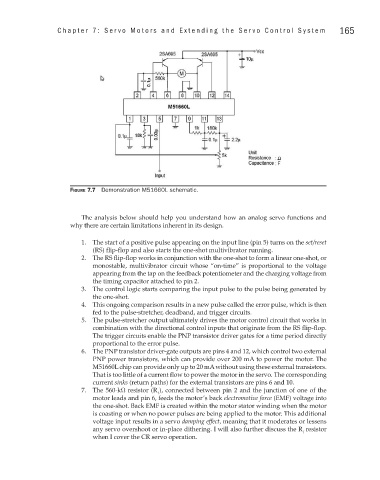
Figure 7.7 Demonstration M51660L schematic.
The analysis below should help you understand how an analog servo functions and
why there are certain limitations inherent in its design.
1. The start of a positive pulse appearing on the input line (pin 5) turns on the set/reset
(RS) flip-flop and also starts the one-shot multivibrator running.
2. The RS flip-flop works in conjunction with the one-shot to form a linear one-shot, or
monostable, multivibrator circuit whose “on-time” is proportional to the voltage
appearing from the tap on the feedback potentiometer and the charging voltage from
the timing capacitor attached to pin 2.
3. The control logic starts comparing the input pulse to the pulse being generated by
the one-shot.
4. This ongoing comparison results in a new pulse called the error pulse, which is then
fed to the pulse-stretcher, deadband, and trigger circuits.
5. The pulse-stretcher output ultimately drives the motor control circuit that works in
combination with the directional control inputs that originate from the RS flip-flop.
The trigger circuits enable the PNP transistor driver gates for a time period directly
proportional to the error pulse.
6. The PNP transistor driver-gate outputs are pins 4 and 12, which control two external
PNP power transistors, which can provide over 200 mA to power the motor. The
M51660L chip can provide only up to 20 mA without using these external transistors.
That is too little of a current flow to power the motor in the servo. The corresponding
current sinks (return paths) for the external transistors are pins 6 and 10.
7. The 560-kΩ resistor (R ), connected between pin 2 and the junction of one of the
f
motor leads and pin 6, feeds the motor’s back electromotive force (EMF) voltage into
the one-shot. Back EMF is created within the motor stator winding when the motor
is coasting or when no power pulses are being applied to the motor. This additional
voltage input results in a servo damping effect, meaning that it moderates or lessens
any servo overshoot or in-place dithering. I will also further discuss the R resistor
f
when I cover the CR servo operation.